Repeater, Communication System, Control Circuit, Connector, and Computer Program

Inactive Publication Date: 2009-01-01
KANSAI TLO KK
View PDF2 Cites 11 Cited by
  • Summary
  • Abstract
  • Description
  • Claims
  • Application Information

AI Technical Summary

Benefits of technology

[0026]According to the computer program of the present invention, in a computer such as a router device having the function to determine the route to send out the packet in the communication network, by being executed as firmware, for example, the computer is operated as the repeater of the present invention, the sending time intervals and the storage capacity reference value is calculated based on the transfer rate target value of the packet having a determined route, the storage capacity reference value thus calculated is set as the storage capacity reference value used as a criterion for deciding discard of the packet, and the packet stored in the storing means at the calculated time intervals is sent out to the communication network. Thus, the time delay shown by the product of the storage capacity becoming the reference value and the sending time intervals can be guaranteed, and the transfer rate can also be guaranteed accordingly.
[0027]According to the repeater, communication system, control circuit, connector and computer program of the present invention, the target value of the transfer rate is read from the packet having a determined route in the communication network to be sent out, the sending time intervals are calculated based on the target value of the transfer rate thus read and a data length of the packet, the target value of the delay time in its own device is determined, the storage capacity reference value becoming a reference value of the storage capacity used as a criterion for deciding discard of the packet is calculated, and the packet stored in the storing means is sent out to the communication network at the calculated sending time intervals. By this structure, sinc

Problems solved by technology

However, packet arrival of high priority traffic in a high load of buffer can not be received by only the aforesaid discipline of scheduling, and a sufficient QoS control can hardly be provided.
However, a buffer management in consideration of the plurality of ports is not fully studied.
However, for example, the conventional method shown in the above document involves a p

Method used


Image

  • Repeater, Communication System, Control Circuit, Connector, and Computer Program
  • Repeater, Communication System, Control Circuit, Connector, and Computer Program
  • Repeater, Communication System, Control Circuit, Connector, and Computer Program

Examples


embodiment 1

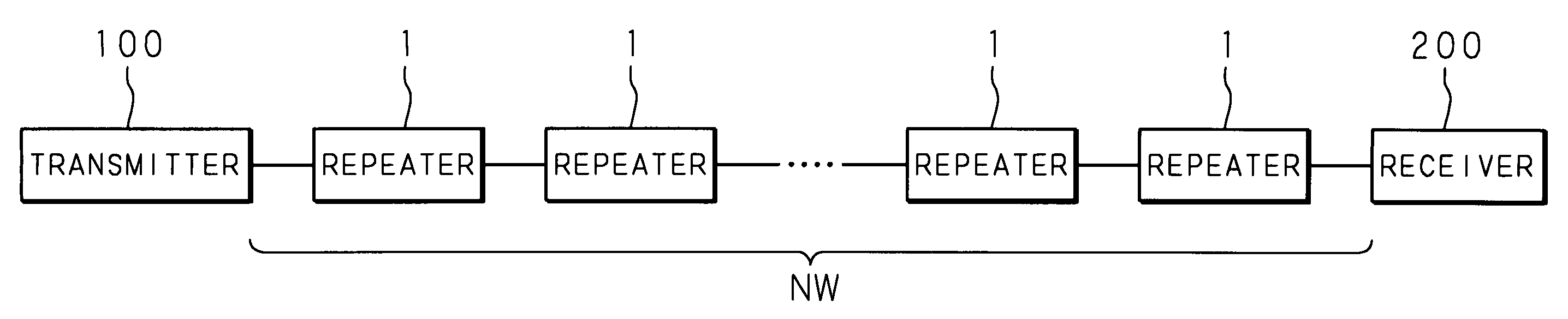
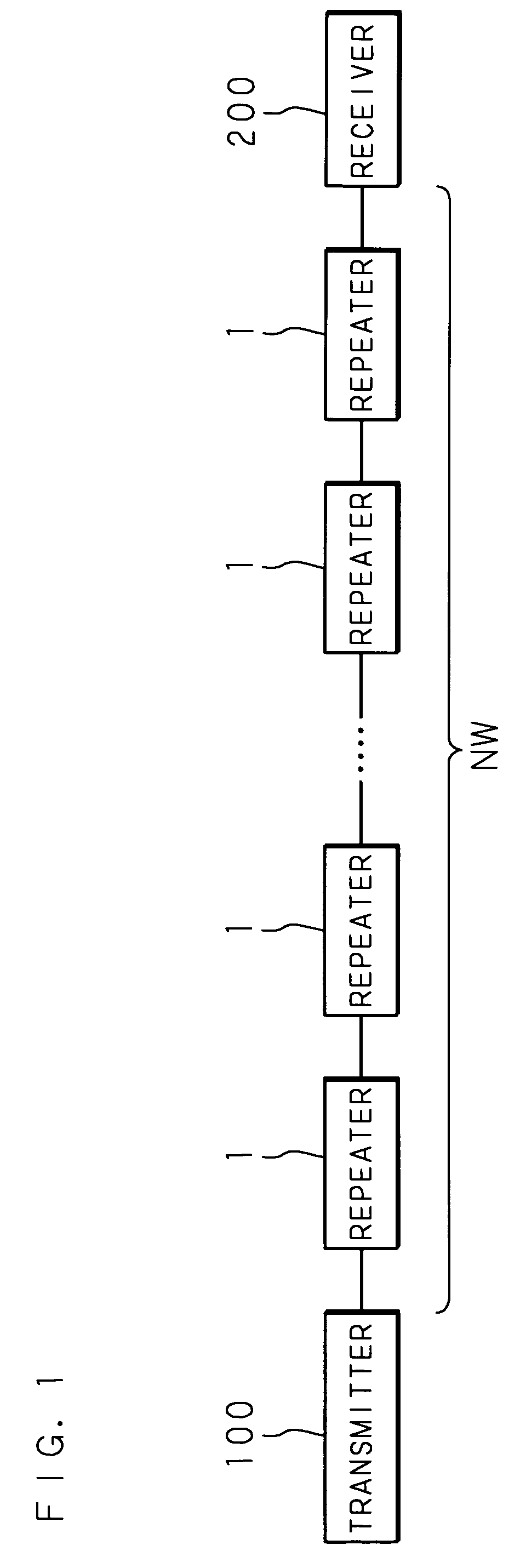
[0048]FIG. 1 is a block diagram showing a constitution of a communication system in an embodiment 1 of the present invention. Reference numerals 1, 1, . . . in FIG. 1 denote repeaters of the present invention such as an internet router device. Each repeater 1, 1, . . . is connected to each other by a communication network NW such as the Internet or an intranet. Then, each repeater 1, 1, . . . receives a packet to be transmitted to a receiver 200, which is a device of receiver of the packet, from a transmitter 100, which is a device of sender of the packet, via the communication network NW, determines a route in the communication network NW to transfer the received packet, and performs a route determination process and a packet repeating operation to send out the packet to the communication network NW by the determined route.

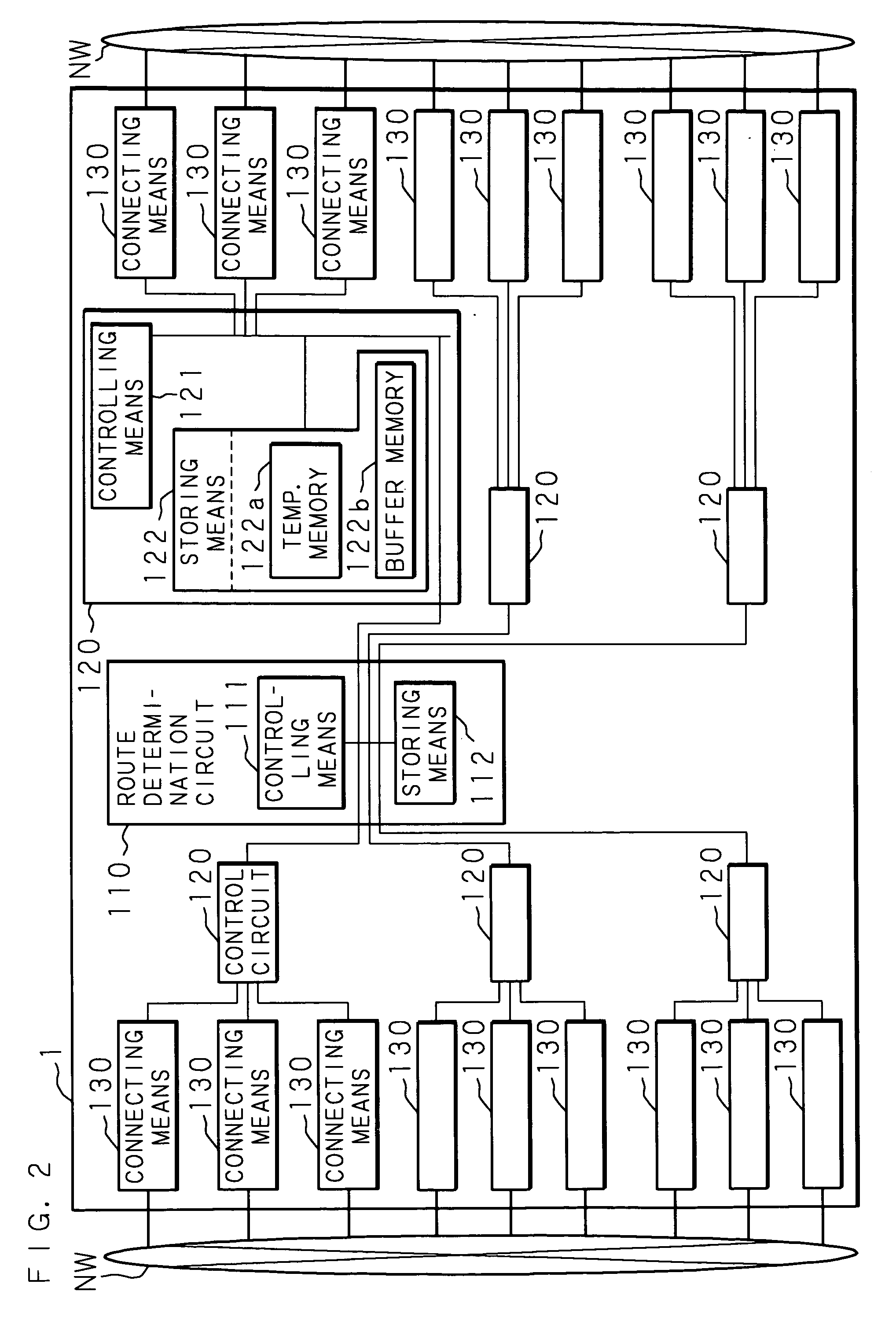
[0049]FIG. 2 is a block diagram showing the constitution of the repeater 1 in the embodiment 1 of the present invention. The repeater 1 comprises a route determi...

embodiment 2

[0091]FIG. 11 is a block diagram showing the connector and the repeater having the connector connected thereto according to the embodiment 2 of the present invention. In FIG. 11, connectors of the present invention are identified as reference numerals 2, 2. The connector 2 is connected to a repeater 3 such as an internet router device which receives the packet to be transmitted from the device of sender to the device of receiver via the communication network NW, and having a route determining function to determine the route in the communication network NW for transmitting the received packet, via communication line L such as cable for Ethernet (registered trademark).

[0092]The connector 2 comprises the controlling means 21 such as a CPU, the storing means 22 such as a RAM, first connecting means 23, 23, . . . connected to, and the repeater 3, via communication line L, and second connecting means 24, 24, . . . connected to the communication network NW. Then, by the control of the cont...

embodiment 3

[0111]FIG. 16 is a block diagram showing the repeater according to an embodiment 3 of the present invention. Identified as reference numeral 4 in FIG. 16 is the repeater. The repeater 4 comprises a controlling means 41 such as a CPU, storing means 42 such as a RAM, recording means 43 such as a flush memory, and connecting means 44 connected to the communication network NW. A computer program PG of the present invention is recorded in the recording means 43 as firmware. The repeater 4 is a kind of computer such as an internet router device comprising a route determination function which is the function to receive the packet to be transmitted to the device of receiver from the device of sender via the communication network NW and determine the route in the communication network NW to transmit the received packet. The repeater 4 can realize the same function as that of the repeater 1 according to the embodiment 1 of the present invention, by reading the computer program PG of the prese...


PUM


Abstract

A repeater such as an Internet router device used in a communication network such as the Internet. The delay time from a device of a sender to a device of a receiver is secured. A communication system, a control circuit, a connecting means, and a computer program are also disclosed. The sending time intervals between sending to a transmission network are calculated from a target value of the transfer rate of a packet to be relayed (S202), a target value of the delay time is determined on the basis of the delay time to be secured (S205), and a reference value of the storage capacity used as a criterion for deciding discard of a packet is calculated from the delay time target value and the sending time intervals (S206). Packets are sent out at the calculated sending time intervals, and discard of a packet is judged according to a predetermined method when a packet having a storage capacity above the storage capacity reference value is received.

Description

BACKGROUND OF THE INVENTION[0001]1. Field of the Invention[0002]The present invention relates to a repeater such as an Internet router device receiving a packet through a communication network such as the Internet, determining a route in the communication network to send out the packet, a repeater such as a router device performing routing processing to send out the packet to the communication network on the determined route, a communication system using the repeater, a control circuit controlling the repeater, a connector connected to the repeater, and a computer program for realizing the repeater. Particularly the present invention relates to a repeater guaranteeing QoS in the communication network, the communication system, the control circuit, the connector, and the computer program.[0003]2. Description of Related Art[0004]In recent years, a high performance computer has been widely used not only in research institutes and companies, but also in ordinary houses, and it starts to...

Claims


Application Information

Patent Timeline
IPC IPC(8): H04L12/56
CPCH04L47/10H04L47/32H04L47/283
Inventor MURAKAMI, KOSOTODE, HIDEKIMASAKI, TOSHIHIROKINOSHITA, KAZUHIKO
Owner KANSAI TLO KK
Why Eureka
Try Eureka