Ear Speaker Device

Inactive Publication Date: 2009-02-26
SONY CORP
View PDF6 Cites 18 Cited by
  • Summary
  • Abstract
  • Description
  • Claims
  • Application Information

AI Technical Summary

Benefits of technology

[0012]According to the aspect of the present invention, when the ear speaker device is mounted on or dismounted from the head of the listener, the speaker sections can be temporarily moved in outward directions so as to prevent interference with the auricles and the like. At the same time, when the ear speaker device is mounted on the head, the sound emission surfaces of the speaker units are positioned in front of the openings of the external acous

Problems solved by technology

Also, the surrounding space is open and thus low frequency sound of the reproduction sound

Method used


Image

  • Ear Speaker Device
  • Ear Speaker Device
  • Ear Speaker Device

Examples


Embodiment Construction

[0030]Hereinafter, an embodiment of the present invention will be described in detail with respect to the accompanying drawings.

(1) Structure of Ear Speaker Device

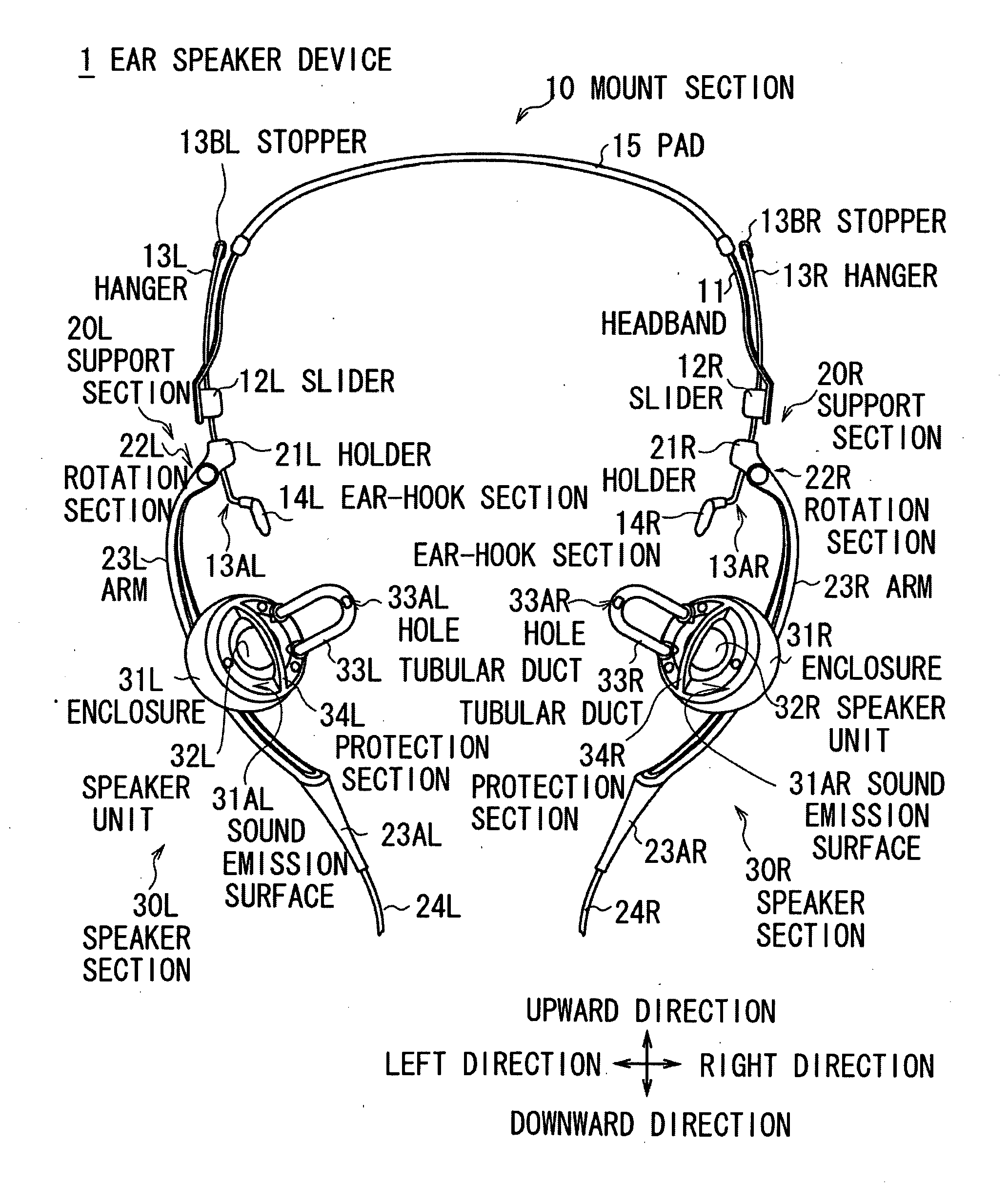
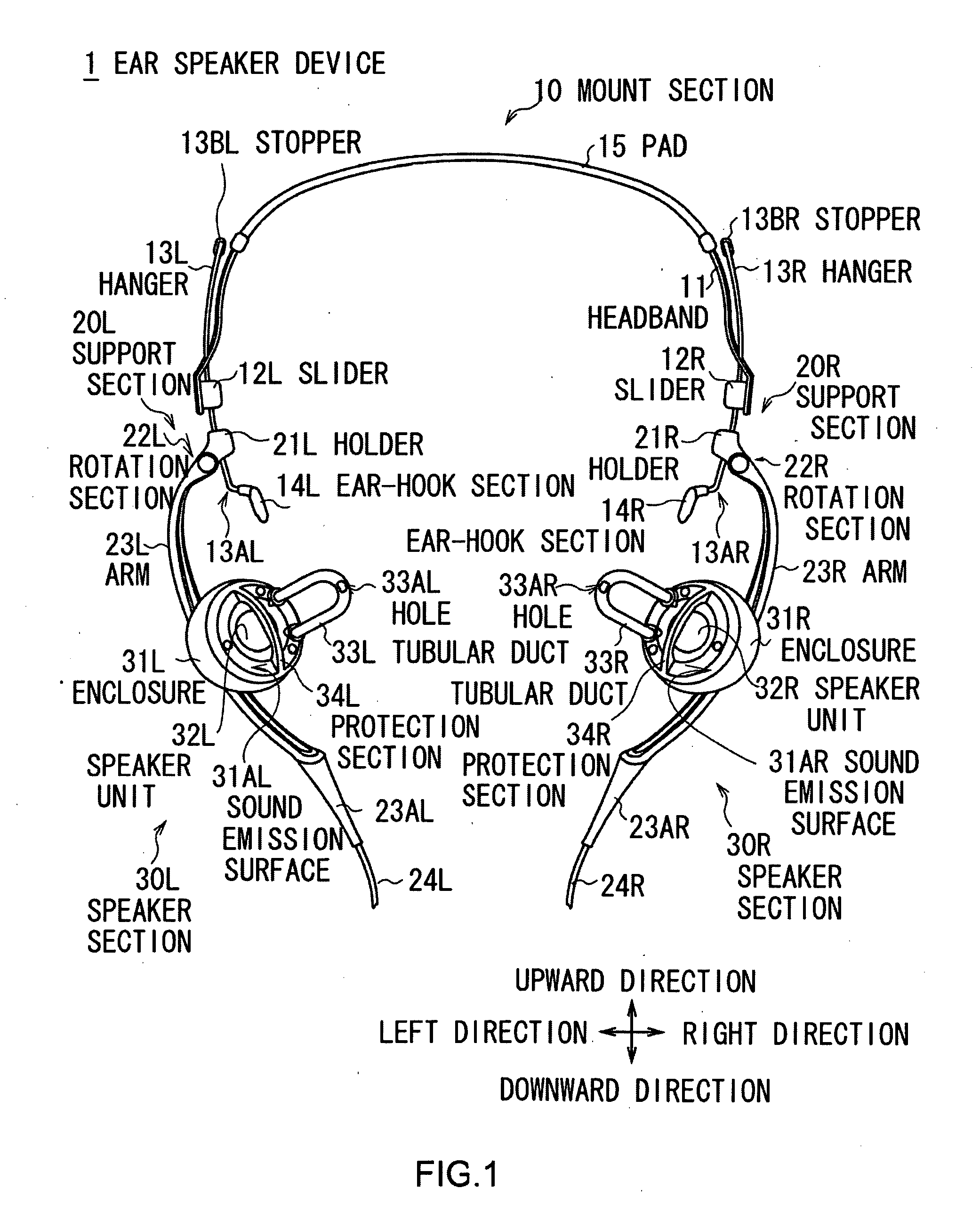
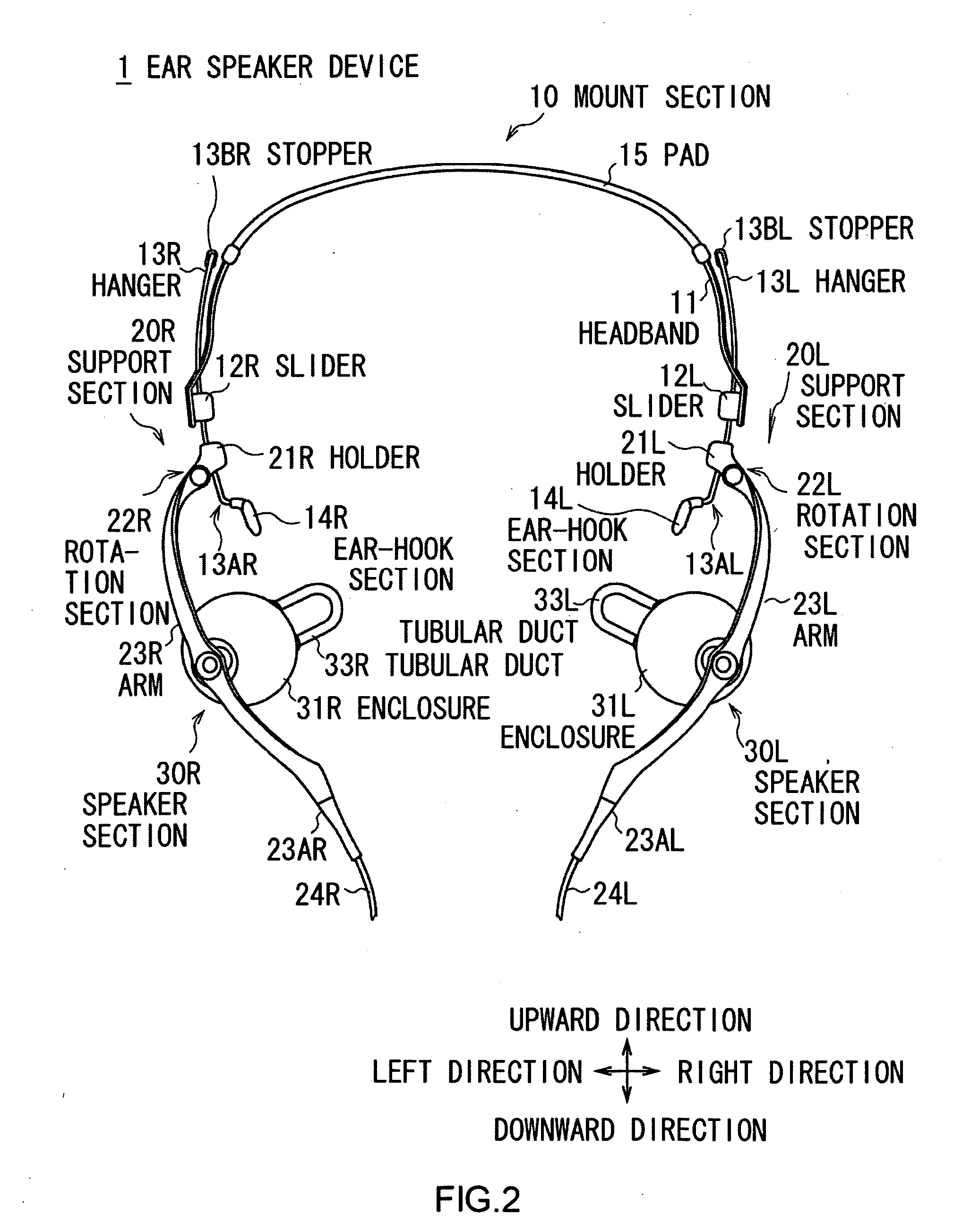
[0031]In FIGS. 1, 2, and 3, an ear speaker device 1 converts an electric signal generated by reproduction processing and the like of a portable compact disc (CD) player and a digital music player (DMP) to sound, and allows a listener to listen to such sound.

[0032]Unlike a general box speaker device, the ear speaker device 1 is assumed to be mounted on the head of the listener like a headphone device. In actuality, the ear speaker device 1 roughly includes a mount section 10, left and right speaker sections 30L and 30R, and support sections 20L and 20R. The mount section 10 is used for mounting the ear speaker device 1 on the head of the listener in a stable manner. The speaker sections 30L and 30R convert an electric signal to sound (hereinafter referred to as reproduction sound). The support sections 20L and 20R are attac...


PUM


Abstract

The ear speaker device includes a mount section that is provided with ear-hook sections, and rotation sections that rotate speaker movable sections with respect to the mount section. Tubular ducts are positioned more inside than the ear-hook sections in a natural state. When the ear speaker device is mounted, the speaker movable sections are rotated to the most outside positions. Then, the ear-hook sections are brought into contact with auricle base upper sections, respectively, and the speaker movable sections are rotated inwardly. In this manner, the tubular ducts can be positioned in the vicinity of the external acoustic meatus openings, respectively, of the listener without interfering with auricles and the like.

Description

CROSS REFERENCES TO RELATED APPLICATIONS[0001]The present invention contains subject matter related to Japanese Patent Application JP2007-219090 filed in the Japanese Patent Office on Aug. 24, 2007, the entire contents of which being incorporated herein by reference.BACKGROUND OF THE INVENTION[0002]1. Field of the Invention[0003]The present invention relates to an ear speaker device, and is suitably applied to, for example, an ear speaker device that mounts a speaker on the head of a listener.[0004]2. Description of the Related Art[0005]As a known headphone device having a structure that is close to a head mount type ear speaker device, one that converts an electric signal representing reproducing sound of a compact disc (CD) to a sound (hereinafter referred to as reproduction sound) in a state where the headphone device is mounted on the head of a listener so as to allow the listener to listen to the reproduction sound has been widely used.[0006]A generally-used headphone device po...

Claims


Application Information

Patent Timeline
IPC IPC(8): H04R1/02
CPCH04R1/1058H04R5/0335H04R1/2819H04R1/1066
Inventor YAMAGUCHI, YUKIMASAYAMAGISHI, MAKOTOSUZUKI, SATOSHI
Owner SONY CORP
Why Eureka
Try Eureka