Device latch hook and attachment device including the same

a technology of device latch and attachment device, which is applied in the direction of snap fasteners, coupling device connections, sport apparatus, etc., can solve the problems of difficult to increase the size of the hook, improve the strength of the hook, and the hook is likely to be broken, so as to reduce the possibility of the ring portion being broken, prevent the ring portion from being broken, and improve the impact resistance of the hook

Inactive Publication Date: 2009-03-19
NINTENDO CO LTD
View PDF23 Cites 14 Cited by
  • Summary
  • Abstract
  • Description
  • Claims
  • Application Information

AI Technical Summary

Benefits of technology

[0024]According to the third aspect, compared to a case where the slit is provided at a side where the ring portion and the arm are connected to each other, it is possible to reduce a possibility of the ring portion being broken.
[0025]According to the fourth to sixth aspects, the two forearm portions of the ring portion grasp the spindle. Accordingly, when a tensile force from the arm is applied to the ring portion while the ring portion is pivoted by the spindle, the two forearm portions are deformed so as to open out. Therefore, it is possible to prevent the ring portion from being broken.
[0026]According to the seventh aspect, with the attachment device having a hook which is the same as that of the first aspect, it is possible to firmly fix the attachment device to the electronic apparatus, and also possible to improve the impact-resistance of the hook. Further, according to the seventh aspect, with an operation of the button, it is possible to disengage the hook, which is la

Problems solved by technology

In the case of the conventional hook, when a strong impact is applied to the electronic apparatus and the attachment device, a strong force is applied to the hook, and as a result, the hook is likely to be broken.
Particularly in the case of a hand-held device, s

Method used


Image

  • Device latch hook and attachment device including the same
  • Device latch hook and attachment device including the same
  • Device latch hook and attachment device including the same

Examples


Embodiment Construction

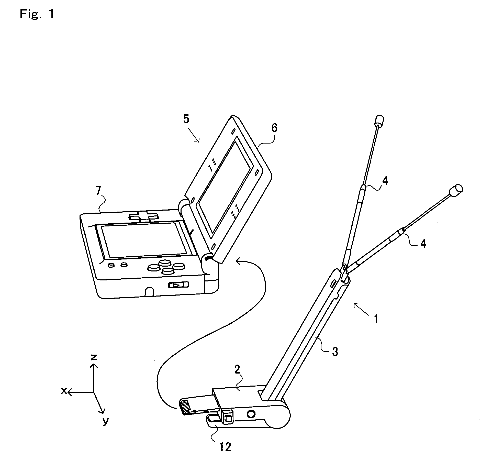
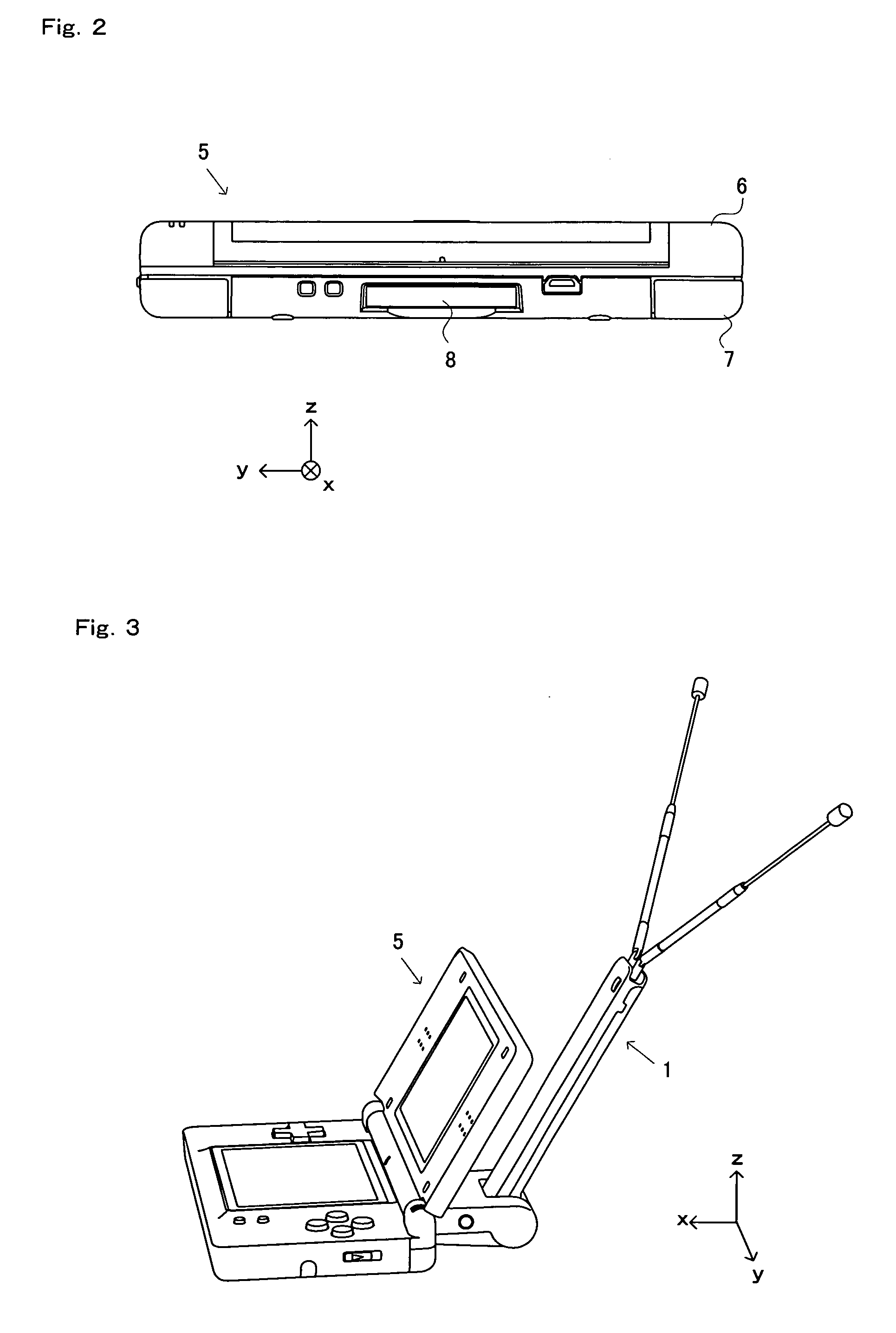
[0050]Hereinafter, a device latch hook and an attachment device according to one embodiment of the present invention will be described. In the present embodiment, a case will be described where an electronic apparatus into which the attachment device is mounted is a hand-held game apparatus, and the attachment device is a cartridge capable of receiving digital broadcasting. The present invention is also applicable to other apparatuses and devices than the above-described game apparatus and cartridge. For example, the electronic apparatus into which the attachment device is mounted may be replaced with a portable terminal such as a portable phone and a PDA. Further, the attachment device may be a storage medium (such as a memory card) having a predetermined application (program) stored thereon, or may be a storage medium for storing data generated in the electronic apparatus. Still alternatively, the attachment device may be a cartridge for causing the electronic apparatus to expand ...


PUM


Abstract

A hook 14 causes an attachment device (cartridge), which is mounted into an insertion slot arranged in an electronic apparatus such as a game apparatus, to be engaged with the insertion slot. The hook includes an arm 22, a ring portion 21 and a latch portion 23. The ring portion 21 is connected to one end of the arm 22. The latch portion 23 is connected to the other end of the arm22, and is latchable onto a predetermined portion of the insertion slot. Further, the ring portion 21 is pivoted by a spindle 31 of the attachment device, and is shaped so as to be deformable when a force from the arm 22 is applied thereto, the force being caused by the attachment device moving so as to be ejected from the insertion slot.

Description

CROSS REFERENCE TO RELATED APPLICATION[0001]The disclosure of Japanese Patent Application No. 2007-238071, filed Sep. 13, 2007, is incorporated herein by reference.BACKGROUND OF THE INVENTION[0002]1. Field of the Invention[0003]The present invention relates to a device latch hook, an attachment device and an electronic apparatus system. The present invention more particularly relates to a device latch hook provided to an attachment device so as to prevent the attachment device which is inserted in an insertion slot of an electronic apparatus from being disengaged from the insertion slot, and the attachment device and an electronic apparatus system which include the device latch hook.[0004]2. Description of the Background Art[0005]Conventionally, a mechanism for mounting an attachment device such as a memory card into an electronic apparatus such as a hand-held device has been developed. For example, in Patent document 1 (Japanese Laid-Open Patent Publication No. 06-44413), a mechani...

Claims


Application Information

Patent Timeline
IPC IPC(8): A44B21/00A44B99/00H01R12/73
CPCY10T24/44291A63F2300/1043Y10T24/44342A63F13/02Y10T292/0911Y10T292/1051A63F13/98
Inventor KAMADA, HIROSHIYONEYAMA, KAZUOAMANO, MASAKI
Owner NINTENDO CO LTD
Why Eureka
Try Eureka