Automatic focusing device

Active Publication Date: 2009-03-19
XACTI CORP
View PDF4 Cites 22 Cited by
  • Summary
  • Abstract
  • Description
  • Claims
  • Application Information

AI Technical Summary

Benefits of technology

[0024]As described, according to the automatic focusing device of the present invention, the correspondence between the autofocus evaluation value and the focus lens posit

Problems solved by technology

However, this tentative focus lens position does not correspond to the autofocus evaluation value of the frame accurately, and therefore there has been

Method used


Image

  • Automatic focusing device
  • Automatic focusing device
  • Automatic focusing device

Examples


Embodiment Construction

[0029]In a preferred embodiment discussed in detail below with reference to drawings, an automatic focusing device of the present invention is implemented in a digital camera.

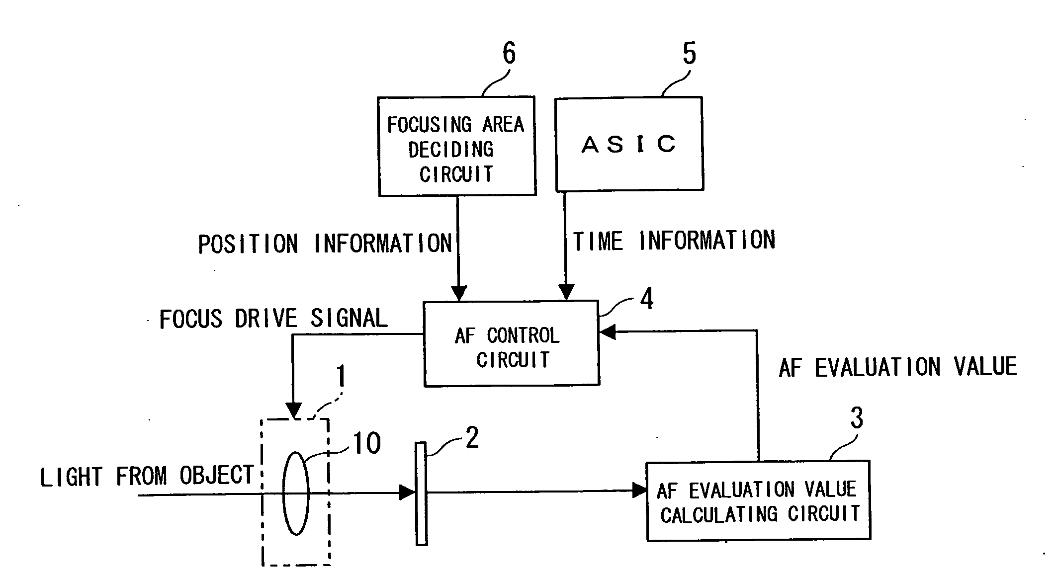
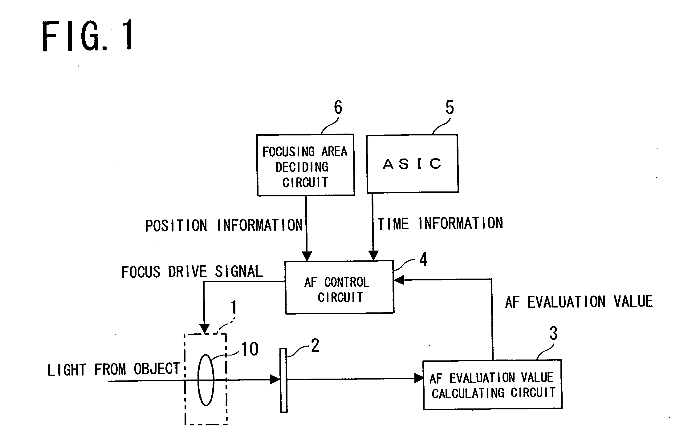
[0030]As shown in FIG. 1, a digital camera according to the present invention comprises a focusing system 1 including a focus lens 10 through which light from an object passes, an image sensor 2 comprising a CMOS sensor into which the light is introduced after passing through the focus lens 10, an AF evaluation value calculating circuit 3 calculating an autofocus evaluation value (AF evaluation value) based on an imaging signal obtained from the image sensor 2, and an AF control circuit 4 producing a focus drive signal based on the AF evaluation value obtained from the AF evaluation value calculating circuit 3 and providing the signal to the focusing system 1. With this structure, in the focusing system 1, the focus lens 10 is driven in the optical axis direction, whereby the focusing operation is conducted. In...


PUM


Abstract

An automatic focusing device in accordance with the present invention comprises an image sensor being subjected to exposure performed in a rolling shutter system, a focusing system including a focus lens for focusing on the image sensor, an AF evaluation value calculating unit calculating an AF evaluation value based on an imaging signal obtained from the image sensor, and an AF control unit controlling an operation of the focusing system based on an AF evaluation value of a focusing area set in a part of the imaging picture by the image sensor, and the AF control unit makes the AF evaluation value of a focusing area of each imaging picture and a focus lens position at the time of exposure for the focusing area correspond to each other, and drives the focusing system during the period which overlaps with an exposure period while searching the focus lens position where the AF evaluation value becomes maximum.

Description

[0001]The priority application Number 2007-244534 upon which this patent application is based is hereby incorporated by reference.BACKGROUND OF THE INVENTION[0002]1. Field of the Invention[0003]The present invention relates to automatic focusing devices conducting a focusing operation in accordance with imaging signals obtained from an image sensor, such as CMOS sensor, and provided in imaging devices such as a digital camera or a digital video camera.[0004]2. Description of Related Art[0005]Conventionally, in a digital camera provided with a CMOS sensor as an imaging device, while a frame period V is repeated as shown in FIG. 4, an exposure is performed at every horizontal scanning line sequentially from the highest horizontal scanning line La to the lowest horizontal scanning line Lb of an imaging picture obtained by the CMOS sensor. As a result, imaging signals for one frame are obtained by the CMOS sensor. This exposure system is called a rolling shutter system.[0006]In the imag...

Claims


Application Information

Patent Timeline
IPC IPC(8): G03B13/00
CPCG03B13/36H04N5/3532H04N5/23212H04N23/673H04N25/531
Inventor YUBA, MOTOHIROTSUJINO, KAZUHIROFUJIWARA, TAKESHI
Owner XACTI CORP
Why Eureka
Try Eureka