Vehicle body structure

a technology for vehicle body and body, applied in the field of structure, can solve the problem of not substantially increasing the weight of the vehicle body

Inactive Publication Date: 2009-04-23
HONDA MOTOR CO LTD
View PDF25 Cites 30 Cited by
  • Summary
  • Abstract
  • Description
  • Claims
  • Application Information

AI Technical Summary

Benefits of technology

[0019]It is also preferred that the opening be set to a shape and size that...

Problems solved by technology

Moreover, since the configuration involves merely connecting the pair of reinforcing members together by means ...

Method used


Image

  • Vehicle body structure
  • Vehicle body structure
  • Vehicle body structure

Examples


first embodiment

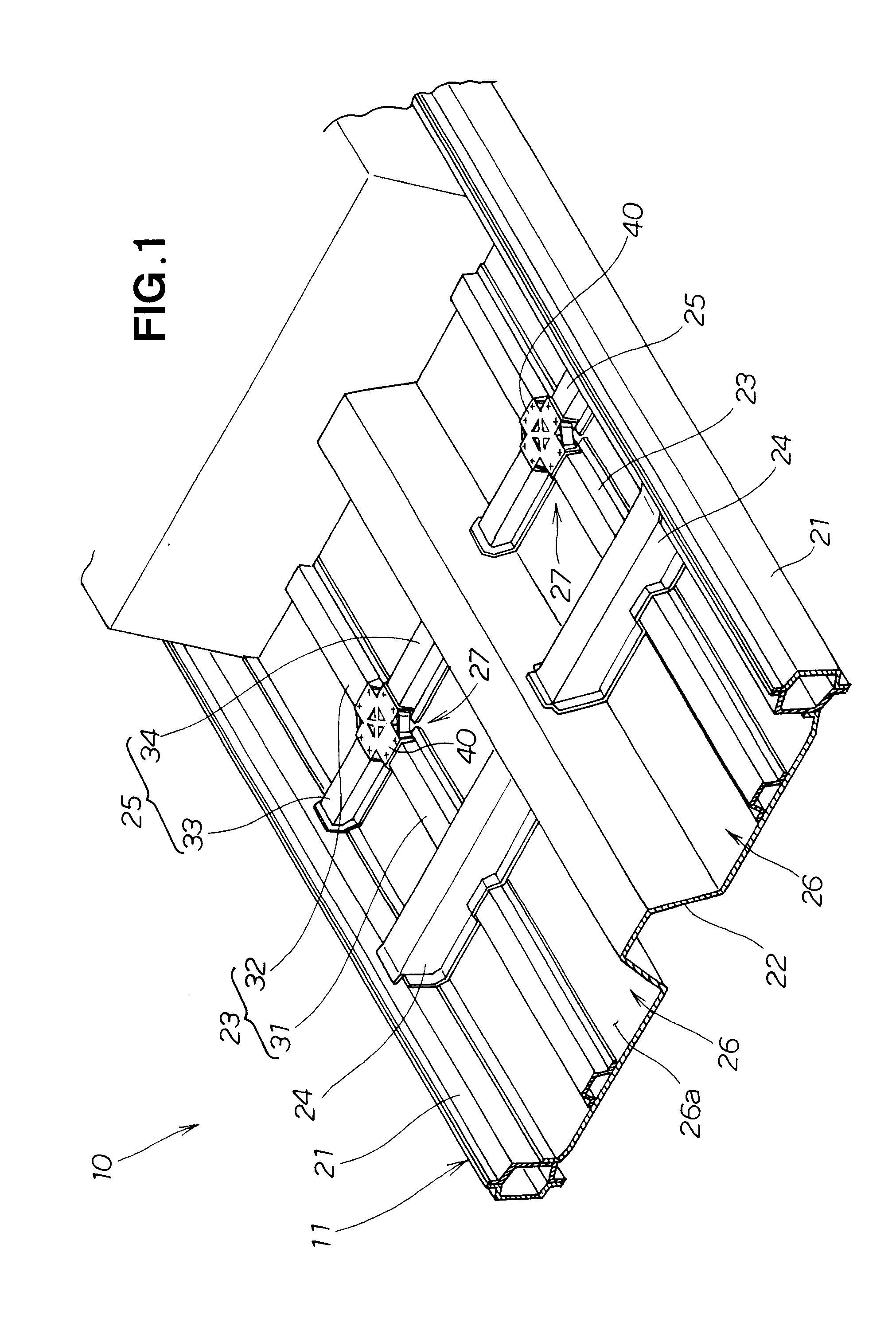
[0035]First, the vehicle body structure of the first embodiment will be described with reference to FIGS. 1 through 7.

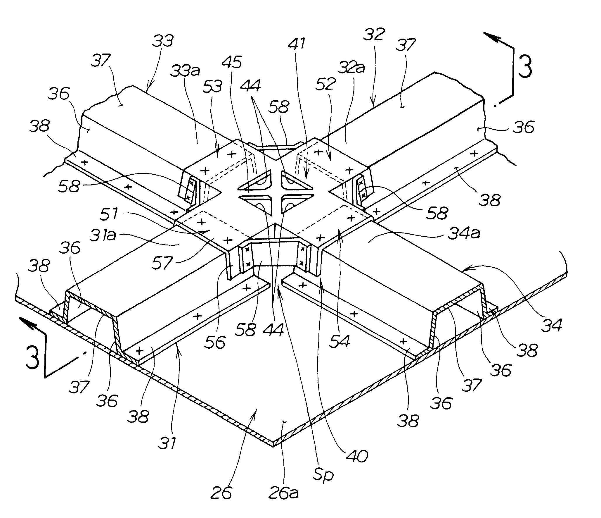
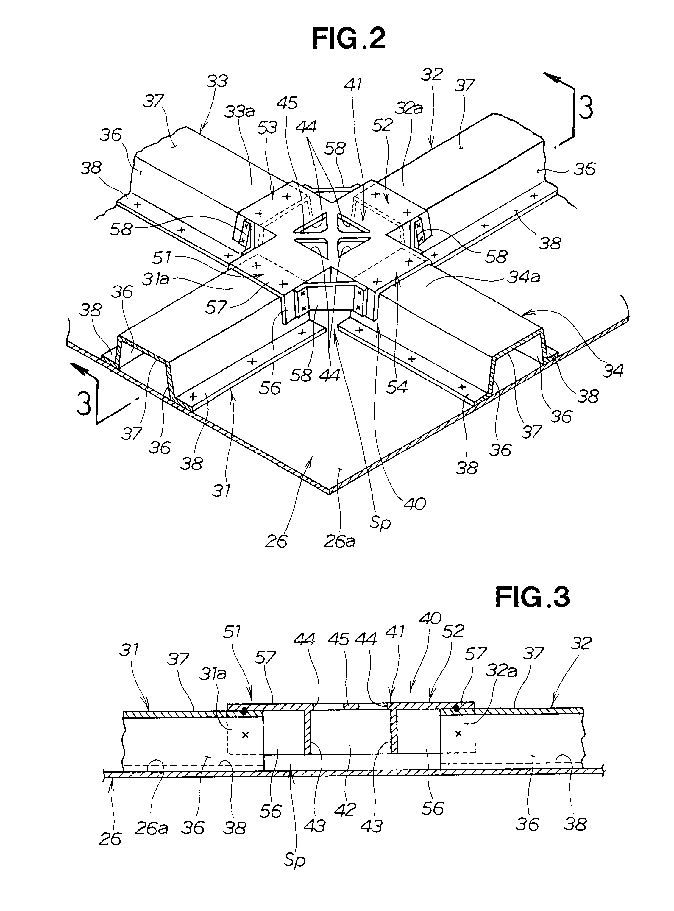
[0036]A vehicle body 11 in an automobile or another vehicle 10 comprises a monocoque body, as shown in FIG. 1. The configuration of the center portion of the vehicle body 11 (passenger compartment portion) has left and right side sills 21, 21, a floor tunnel 22, left and right floor frames 23, 23, two front and rear cross members 24, 25, and front floor panels 26, 26.

[0037]The left and right side sills 21, 21 are members that are positioned on the left and right sides of the vehicle body 11 and that extend in the longitudinal direction of the vehicle body 11. The floor tunnel 22 is a member that is positioned in the center of the vehicle width and that extends in the longitudinal direction of the vehicle body 11. The left and right floor frames 23, 23 are members that are positioned to the left and right sides of the floor tunnel 22 and that extend in the longitudina...

second embodiment

[0068]Next, the vehicle body structure of the second embodiment will be described with reference to FIGS. 10 through 14.

[0069]A vehicle body 111 in an automobile or another vehicle 100 comprises a monocoque body, as shown in FIG. 10. The configuration of the center portion of the vehicle body 111 (passenger compartment portion) comprises left and right side sills 121, 121, a floor tunnel 122, two front and rear cross members 123, 124, front floor panels 125, 125, and left and right floor beads 126, 126.

[0070]The left and right side sills 121, 121 are members that are positioned on the left and right sides of the vehicle body 111 and that extend in the longitudinal direction of the vehicle body 111. The floor tunnel 122 is a member that is positioned in the center of the vehicle width and that extends in the longitudinal direction of the vehicle body 111. The front and rear cross members 123, 124 are members that extend in the vehicle width direction and that span between the side si...


PUM


Abstract

A vehicle body structure in which a panel is reinforced by a pair of reinforcing members, and a connecting member is included. The pair of reinforcing members intersects with each other and the reinforcing members are provided along one surface of the panel. The connecting member is connected to both of the pair of reinforcing members in a portion where the pair of reinforcing members intersects with each other.

Description

FIELD OF THE INVENTION[0001]The present invention relates to a structure of a vehicle body in a passenger vehicle or another vehicle.BACKGROUND OF THE INVENTION[0002]Japanese Patent Application Laid-Open Publication No. 07-291150 (JP 07-291150 A) discloses a vehicle body in which various reinforcements are implemented in order to increase the rigidity of a floor panel or another such flat panel.[0003]In the vehicle body structure disclosed in JP 07-291150 A, the floor panel is reinforced by a bead that is long and thin in the longitudinal direction of the vehicle body, a bead that is long and thin in the width direction of the vehicle, and a cross member that is long and thin in the width direction of the vehicle.[0004]The bead (longitudinal bead) that is long and thin in the longitudinal direction of the vehicle body and the bead (transverse bead) that is long and thin in the width direction of the vehicle are formed so as to intersect with each other on the surface of the floor pa...

Claims


Application Information

Patent Timeline
IPC IPC(8): B62D25/20
CPCB62D25/025B62D25/20Y10T403/349Y10T403/345B62D25/2036
Inventor GOMI, TETSUYA
Owner HONDA MOTOR CO LTD
Why Eureka
Try Eureka