Camera Module

a technology of camera module and camera body, applied in the field of camera module, can solve the problems of distorted image color, inability of infrared camera to properly photograph images,

Inactive Publication Date: 2009-05-14
LG INNOTEK CO LTD
View PDF3 Cites 9 Cited by
  • Summary
  • Abstract
  • Description
  • Claims
  • Application Information

AI Technical Summary

Benefits of technology

[0012]A camera module according to an embodiment comprises: a lens barrel having a lens; a housing having an upper portion coupled with the lens barrel; a printed circuit board coupled to a lower portion of the housing and provided thereon with an image sensor and an infrared LED that emits infrared rays; and an infrared cut-off filter positioned above the lens barrel, wherein the infrared cut-off filter is movable to inhibit the infrared rays from being incident into the lens barrel or to allow the infrared rays to be incident into the lens barrel.
[0013]In addition, a camera module according to an embodiment comprises: a lens barrel having a lens; a housing having an upper portion coupled with the lens barrel; a printed circuit board coupled to a lower portion of the housing and provided thereon with an image sensor and an infrared LED that emits infrared rays; an infrared cut-off filter positioned above the lens barrel; a post for supporting the infrared cut-off filter; a guide for providing a moving route of the post; and a handle extending from one side of the post to move the infrared cut-off filter.

Problems solved by technology

However, the conventional infrared camera cannot properly photograph images in day time because sunlight includes infrared rays.
In addition, even if an infrared cut-off filter is installed in the infrared camera to filter visible rays and infrared rays having predetermined bands, a color of an image is distorted when a user photographs the image in day time due to the infrared rays contained in the sunlight.

Method used


Image

  • Camera Module
  • Camera Module
  • Camera Module

Examples


Embodiment Construction

[0016]Hereinafter, preferred embodiments of the present invention will be described with reference to the accompanying drawings. In the following description of the present invention, a detailed description of known functions and configurations incorporated herein will be omitted when it may make the subject matter of the present invention rather unclear.

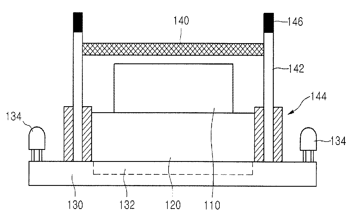
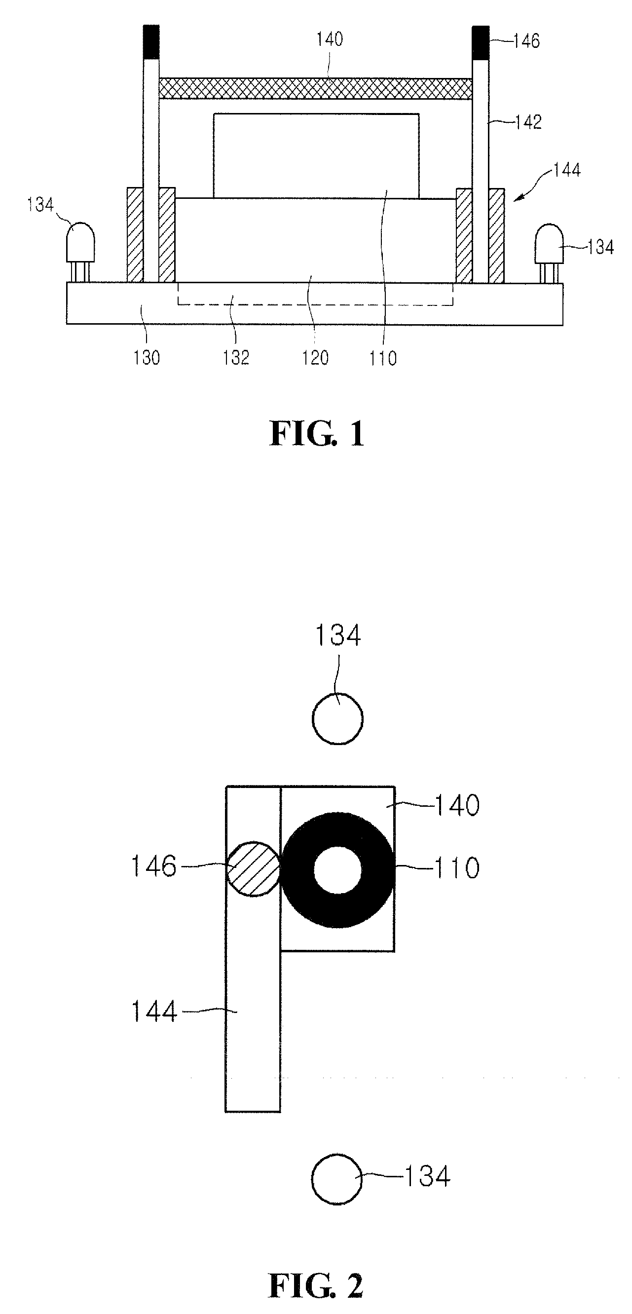
[0017]FIG. 1 is a cross-sectional view showing a camera module according to an embodiment

[0018]Referring to FIG. 1, the camera module according to the embodiment includes a lens barrel 110, in which a plurality of lenses are installed, a housing 120 inserted into an upper opening section of the lens barrel 110, and a printed circuit board 130 coupled with a lower opening section of the housing 120.

[0019]The lens barrel 110 coupled with the upper opening section of the housing 120 serves as a lens holder and is made from resin material, such as polycarbonate.

[0020]A plurality of lenses including apertures and condense lenses are inst...


PUM


Abstract

A camera module according to an embodiment includes a lens barrel having a lens, a housing having an upper portion coupled with the lens barrel, a printed circuit board coupled to a lower portion of the housing and provided thereon with an image sensor and an infrared LED that emits infrared rays, and an infrared cut-off filter positioned above the lens barrel. The infrared cut-off filter is movable to inhibit the infrared rays from being incident into the lens barrel or to allow the infrared rays to be incident into the lens barrel.

Description

CROSS-REFERENCE TO RELATED APPLICATION[0001]The present application claims the benefit under 35 U.S.C. §119 of Korean Patent Application No. 10-2007-0114757, filed Nov. 12, 2007, which is hereby incorporated by reference in its entirety.BACKGROUND[0002]1. Field of the Invention[0003]The embodiment relates to a camera module.[0004]2. Related Art[0005]A closed-circuit television (CCTV) is installed at a specific place to monitor situation of the specific place from a place remote from the specific place.[0006]To this end, the CCTV includes an image transmitter for transmitting images and a display unit for transmitting the image transmitted from the image transmitter to a display device. The display unit can record the image transmitted from the image transmitter or can output a specific image.[0007]A camera used for the conventional CCTV is divided into a general camera, which is used in a place where illumination is constantly maintained, and an infrared camera having a light emitti...

Claims


Application Information

Patent Timeline
Patent Type & Authority Applications(United States)
IPC IPC(8): G02B7/00
CPCG02B5/208H04N5/2257H04N5/2254G02B26/007H04N23/57H04N23/55G03B11/00G03B17/00G03B19/00
Inventor SON, SUNG HO
Owner LG INNOTEK CO LTD
Why Eureka
Try Eureka