Solid electrolytic capacitor

a solid electrolytic capacitor and capacitor technology, applied in the direction of fixed capacitor details, casings/cabinets/drawers, electrical apparatus casings/cabinets/drawers, etc., can solve the problem of low production yield of solid electrolytic capacitors, and achieve the effect of reducing the equivalent series resistance, high accuracy and reliability

Active Publication Date: 2009-06-11
SANYO ELECTRIC CO LTD
View PDF3 Cites 12 Cited by
  • Summary
  • Abstract
  • Description
  • Claims
  • Application Information

AI Technical Summary

Benefits of technology

[0010]The present invention was made to solve the above-described problem, and its object is to provide a solid electrolytic capacitor allowing highly accurate

Problems solved by technology

This leads to lower production yield

Method used


Image

  • Solid electrolytic capacitor
  • Solid electrolytic capacitor
  • Solid electrolytic capacitor

Examples


Embodiment Construction

[0076]Solid Electrolytic Capacitor

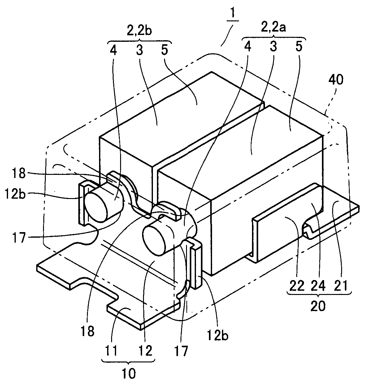
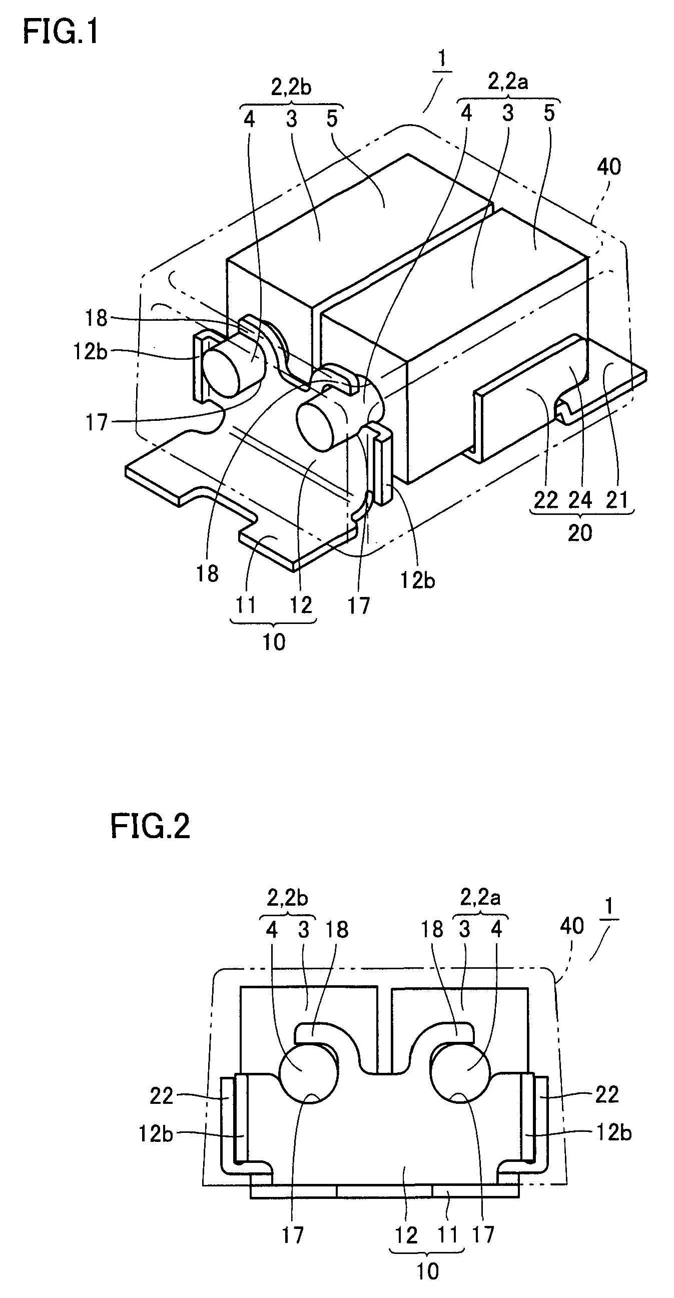
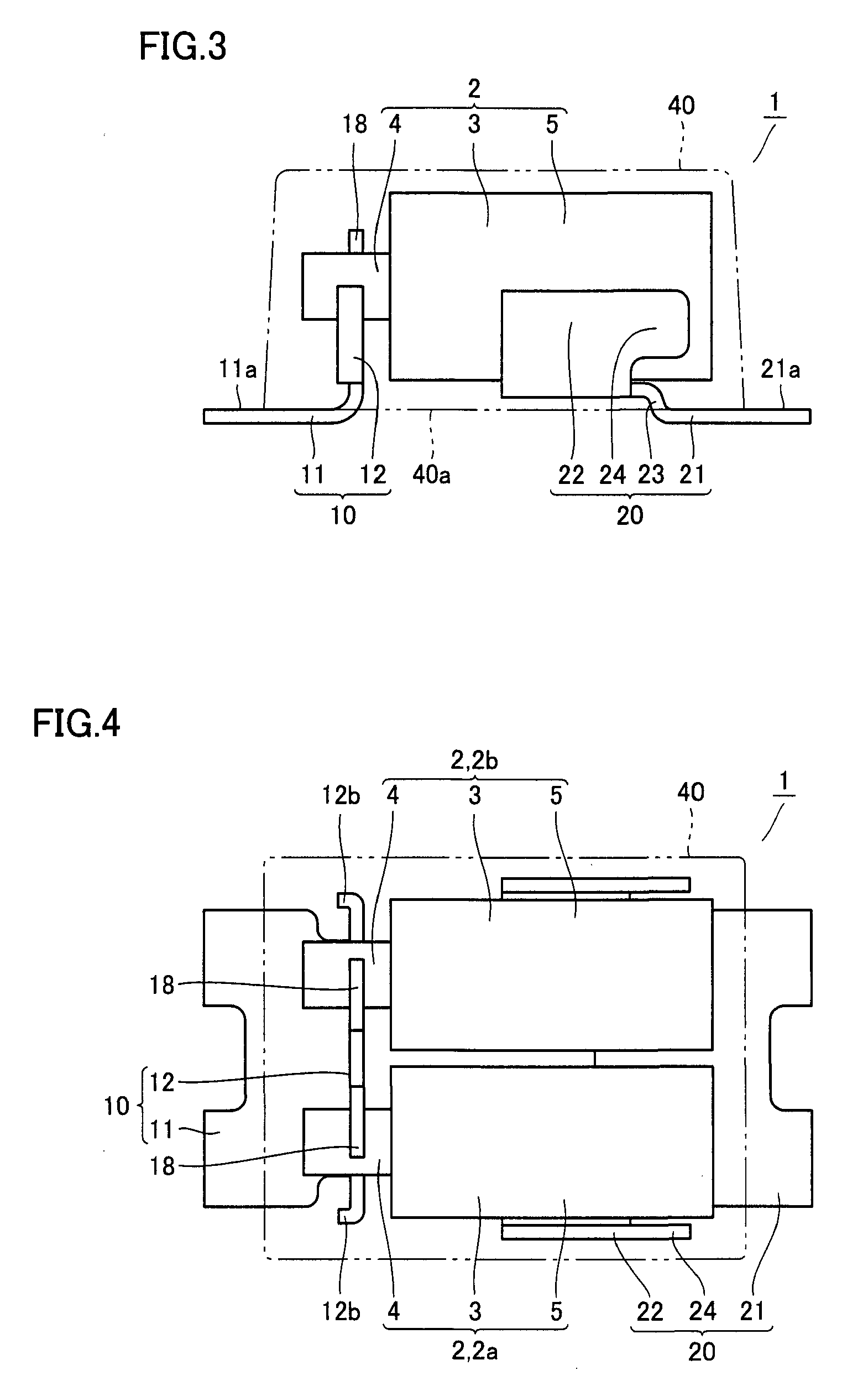
[0077]The solid electrolytic capacitor in accordance with an embodiment of the present invention will be described. As shown in FIGS. 1 to 4, solid electrolytic capacitor 1 includes two capacitor elements 2, 2a, 2b, an anode lead frame 10, a cathode lead frame 20 and mold resin portion 40 sealing these. Capacitor element 2 has a substantially columnar (rectangular parallelepiped) anode body 3, an anode portion 4 protruded from the body, and a cathode portion 5 formed on an outer surface surrounding anode body 3. The two capacitor elements 2a and 2b are arranged with anode portions 4 facing the same direction.

[0078]Anode lead frame 10 has an anode terminal portion 11 and a rising portion 12. Anode terminal portion 11 is exposed along a bottom surface of mold resin portion 40. An upper surface 11a of anode terminal portion 11 is directly in contact with a bottom surface 40a of mold resin portion 40, and upper surface 11a and bottom surface 40a are pos...


PUM


Abstract

A solid electrolytic capacitor includes a capacitor element, an anode lead frame, a cathode lead frame, and a mold resin portion. The anode lead frame includes an anode terminal portion and a rising portion. The rising portion is formed integral with the anode terminal portion, extends from the anode terminal portion through the mold resin and is connected to an anode portion. At the rising portion, a catching portion receiving and supporting the anode portion from below and a hook portion surrounding and holding an outer circumferential surface of the anode portion, with the anode portion received in the catching portion, are formed. Therefore, a solid electrolytic capacitor can be provided, which allows highly accurate attachment of the capacitor element on the lead frame without applying any additional member and reduces equivalent series resistance.

Description

BACKGROUND OF THE INVENTION[0001]1. Field of the Invention[0002]The present invention relates to a solid electrolytic capacitor and, more specifically, to a solid electrolytic capacitor having a capacitor element mounted on a prescribed lead frame and sealed with mold resin portion.[0003]2. Description of the Background Art[0004]A solid electrolytic capacitor is one of electronic components that can be surface-mounted on a printed circuit board or the like. As shown in FIG. 41 or 42, a solid electrolytic capacitor 101 of this type includes a capacitor element 102, an anode lead frame 110, a cathode lead frame 120 and a mold resin portion 140 sealing these components. Capacitor element 102 has a substantially columnar (rectangular parallelepiped) anode body 103, an anode portion 104 protruded from the body, and a cathode portion 105 formed on an outer surface surrounding anode body 103. Anode lead frame 110 is electrically connected to anode portion 104 with a pillow member 180 inter...

Claims


Application Information

Patent Timeline
IPC IPC(8): H01G9/012
CPCH01G9/012H01G9/004H01G9/08H01G9/15
Inventor MATSUOKA, KEIKOUMEDA, SHOJI
Owner SANYO ELECTRIC CO LTD
Why Eureka
Try Eureka