
Solid electrolytic capacitor

a technology of electrolytic capacitors and capacitors, applied in the direction of fixed capacitor details, casings/cabinets/drawers, electrical apparatus casings/cabinets/drawers, etc., can solve problems such as thermal distortion, and achieve the effect of high accuracy and reliable attachmen

Active Publication Date: 2009-06-11
SANYO ELECTRIC CO LTD
View PDF14 Cites 18 Cited by
  • Summary
  • Abstract
  • Description
  • Claims
  • Application Information

AI Technical Summary

Benefits of technology

[0010]The present invention was made to solve the above-described problem, and its object is to provide a solid electrolytic capacitor allowing highly accurate and reliable attachment of the capacitor element on the lead frame without applying any additional member.
[0012]In this structure, the anode portion of the capacitor element is connected, supported from below, to the rising portion formed integral with the anode terminal portion of the anode lead frame. Therefore, as compared with the solid electrolytic capacitor having the pillow member interposed between the lead frame and the anode portion, the additional pillow member becomes unnecessary, and the process step of welding the pillow member to the lead frame becomes unnecessary, whereby manufacturing cost can be reduced. Further, as the through hole is formed at the rising portion of the anode lead frame, the stress generated at the rising portion because of the pressing force applied when the anode portion is welded to the rising portion is alleviated by the through hole, and the heat at the time of welding is radiated by the through hole, alleviating thermal distortion caused by the heat of welding. This helps to prevent deformation of the rising portion, and highly accurate attachment of the capacitor element becomes possible. Further, as the mold resin flows to the through hole, the through hole serves as an anchor, improving closer contact between the anode lead frame and the mold resin portion.
[0014]Therefore, even when the rising portion should melt by the heat when the anode portion is welded to the rising portion of the anode lead frame and a part of the anode portion should go down, it is possible to prevent the anode portion from going down to the through hole.
[0017]Therefore, it becomes possible to reliably prevent deformation or falling of the rising portion because of the pressing force when the anode portion is welded to the rising portion of the anode lead frame. Further, as the side end portion is bent, closer contact to the mold resin portion can be attained.
[0020]Accordingly, the stress generated in the anode lead frame because of the pressing force when the anode portion is welded to the anode lead frame can effectively be alleviated.

Problems solved by technology

Further, as the through hole is formed at the rising portion of the anode lead frame, the stress generated at the rising portion because of the pressing force applied when the anode portion is welded to the rising portion is alleviated by the through hole, and the heat at the time of welding is radiated by the through hole, alleviating thermal distortion caused by the heat of welding.

Method used


Image

  • Solid electrolytic capacitor
  • Solid electrolytic capacitor
  • Solid electrolytic capacitor

Examples


Embodiment Construction

Solid Electrolytic Capacitor

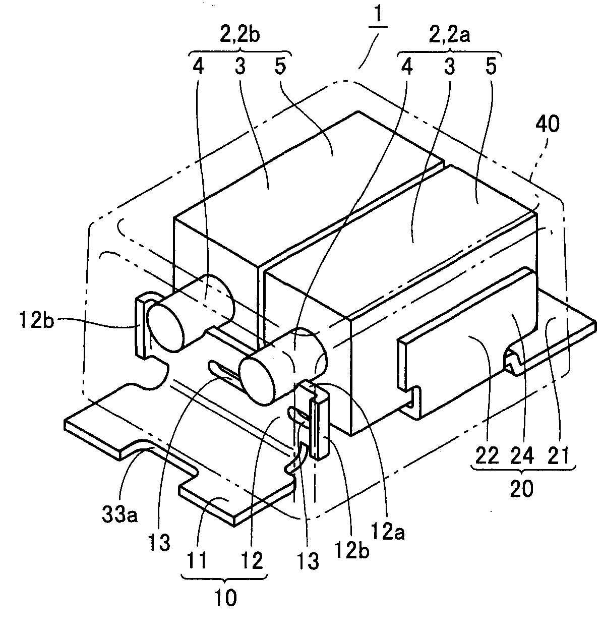
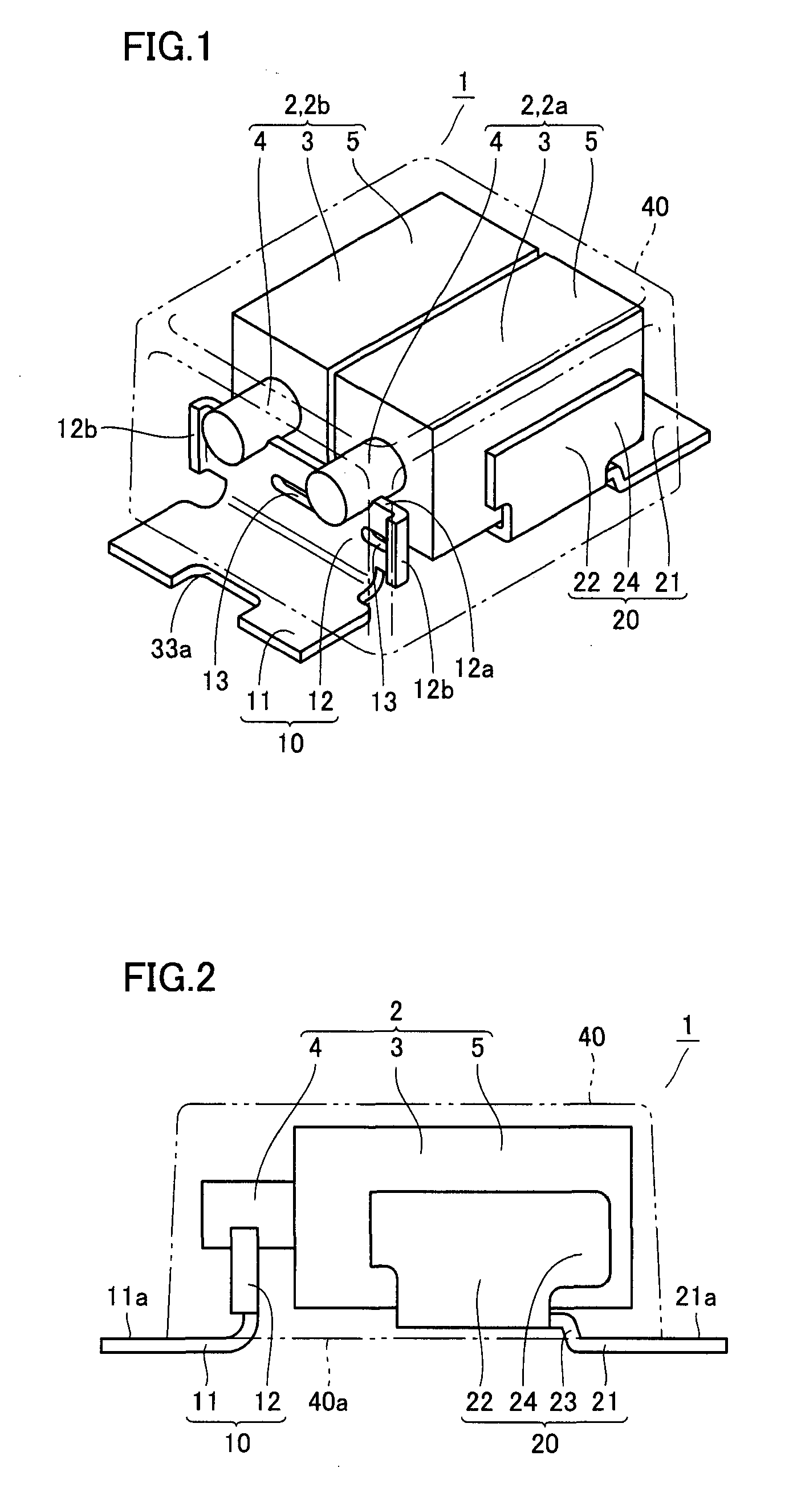
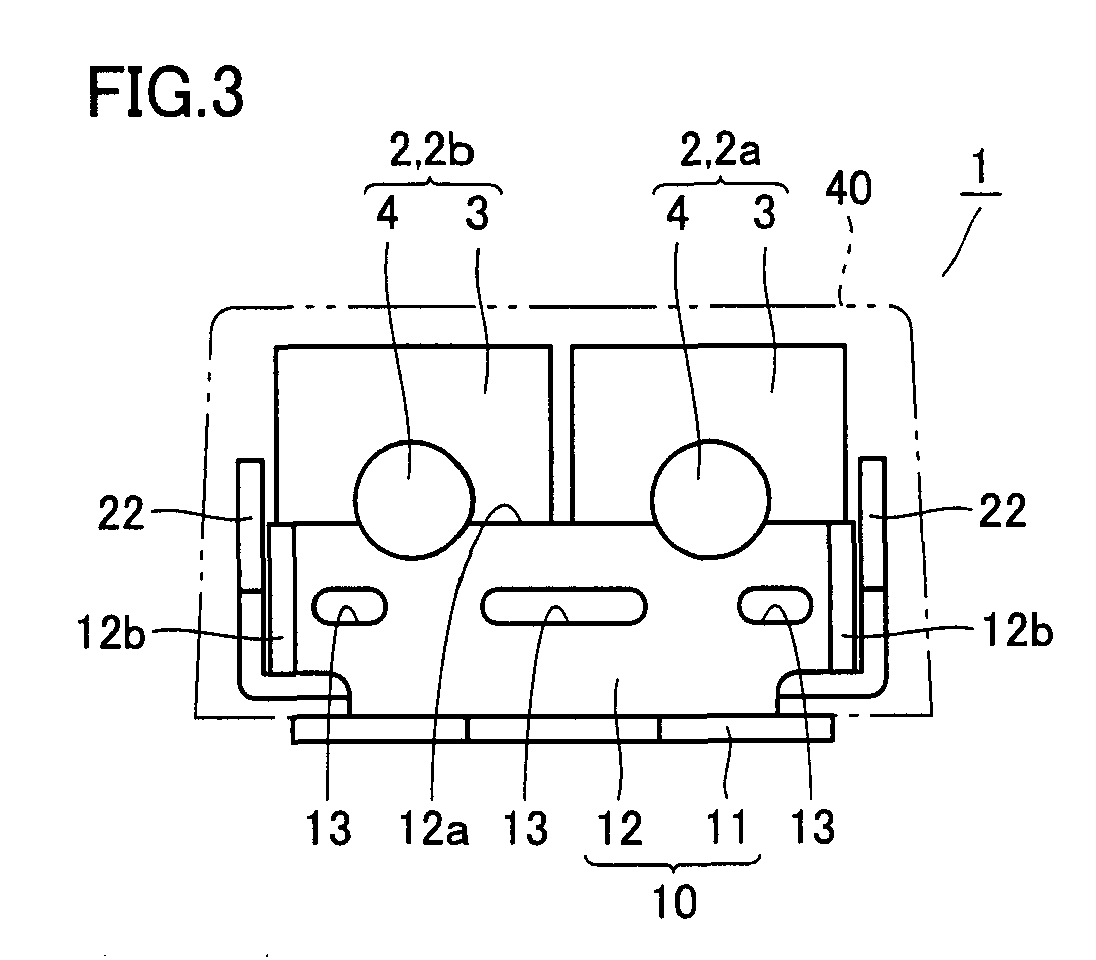
[0041]The solid electrolytic capacitor in accordance with an embodiment of the present invention will be described. As shown in FIGS. 1 to 3, solid electrolytic capacitor 1 includes two capacitor elements 2, 2a, 2b, an anode lead frame 10, a cathode lead frame 20 and a mold resin portion 40 sealing these. Capacitor element 2 has a substantially columnar (rectangular parallelepiped) anode body 3, an anode portion 4 protruded from the body, and a cathode portion 5 formed on an outer surface surrounding anode body 3. The two capacitor elements 2a and 2b are arranged with anode portions 4 facing the same direction.

[0042]Anode lead frame 10 has an anode terminal portion 11 and a rising portion 12. Anode terminal portion 11 is exposed along a bottom surface of mold resin portion 40. An upper surface 11a of anode terminal portion 11 is directly in contact with a bottom surface 40a of mold resin portion 40, and upper surface 11a and bottom surface 40a are positio...


PUM

PropertyMeasurementUnit
shapeaaaaaaaaaa
conductiveaaaaaaaaaa
strengthaaaaaaaaaa

Abstract

A solid electrolytic capacitor includes a capacitor element, an anode lead frame, a cathode lead frame, and a mold resin portion. The anode lead frame includes an anode terminal portion and a rising portion, and the anode terminal portion is exposed at the bottom surface of the mold resin portion. The rising portion is formed integral with the anode terminal portion, and rises to the anode portion. In the rising portion, a through hole is formed. The cathode lead frame includes a cathode terminal portion, a pair of side surface portions and a step portion. Thus, a solid electrolytic capacitor allowing highly accurate and reliable attachment of the capacitor element to the lead frame without using any additional member is provided.

Description

BACKGROUND OF THE INVENTION[0001]1. Field of the Invention[0002]The present invention relates to a solid electrolytic capacitor and, more specifically, to a solid electrolytic capacitor having a capacitor element mounted on a prescribed lead frame and sealed with a mold resin portion.[0003]2. Description of the Background Art[0004]A solid electrolytic capacitor is one of electronic components that can be surface-mounted on a printed circuit board or the like. As shown in FIG. 19, a solid electrolytic capacitor 101 of this type includes a capacitor element 102, an anode lead frame 110, a cathode lead frame 120 and a mold resin portion 140 sealing these components. Capacitor element 102 has a substantially columnar (rectangular parallelepiped) anode body 103, an anode portion 104 protruded from the body, and a cathode portion 105 formed on an outer surface surrounding anode body 103. Anode lead frame 110 is electrically connected to anode portion 104 with a pillow member 180 interpose...

Claims


Application Information

Patent Timeline
Patent Type & Authority Applications(United States)
IPC IPC(8): H01G9/025
CPCH01G9/012H01G9/10Y10T29/417H01G9/14Y10T29/49121H01G9/15H01G9/004H01G9/08
Inventor MATSUOKA, KEIKOUMEDA, SHOJIFUSHIMI, YOSHIYUKITEZUKA, KOJI
Owner SANYO ELECTRIC CO LTD
Learn More