Audio output apparatus and audio output method

Active Publication Date: 2009-08-27
SONY CORP
View PDF4 Cites 21 Cited by
  • Summary
  • Abstract
  • Description
  • Claims
  • Application Information

AI Technical Summary

Benefits of technology

[0008]When listening to music and so on with an in-vehicle audio system while driving when the level of exogenous noise is high, the user may increase the volume of the music

Problems solved by technology

Therefore, the volume level may increase to a level unexpected by the passeng

Method used


Image

  • Audio output apparatus and audio output method
  • Audio output apparatus and audio output method
  • Audio output apparatus and audio output method

Examples


first embodiment

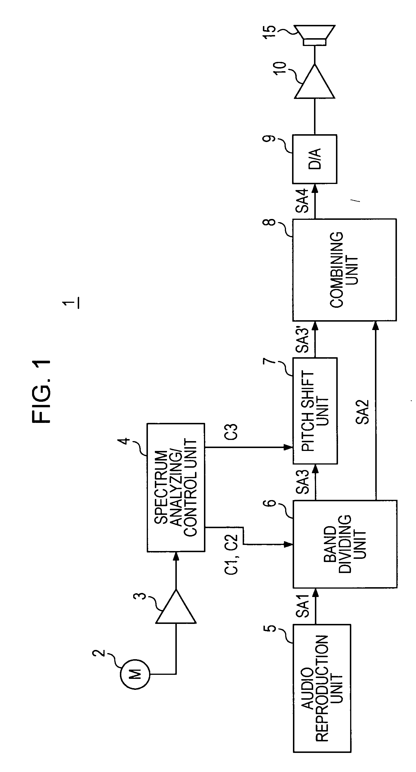
[0036]FIG. 1 illustrates an in-vehicle audio apparatus 1 according to the first embodiment of the present invention.

[0037]The audio apparatus 1 includes a microphone 2, a microphone amplifier 3, a spectrum analysis / control unit 4, an audio reproduction unit 5, a band dividing unit 6, a pitch shift unit 7, a combining unit 8, a D / A converter 9, a power amplifier 10, and a speaker 15.

[0038]The microphone 2 is used to collect noise sensible inside the vehicle, i.e., road noise, and is installed in an appropriate location inside an automobile.

[0039]Noise audio signals acquired by the microphone 2 are supplied to the spectrum analysis / control unit 4 via the microphone amplifier 3.

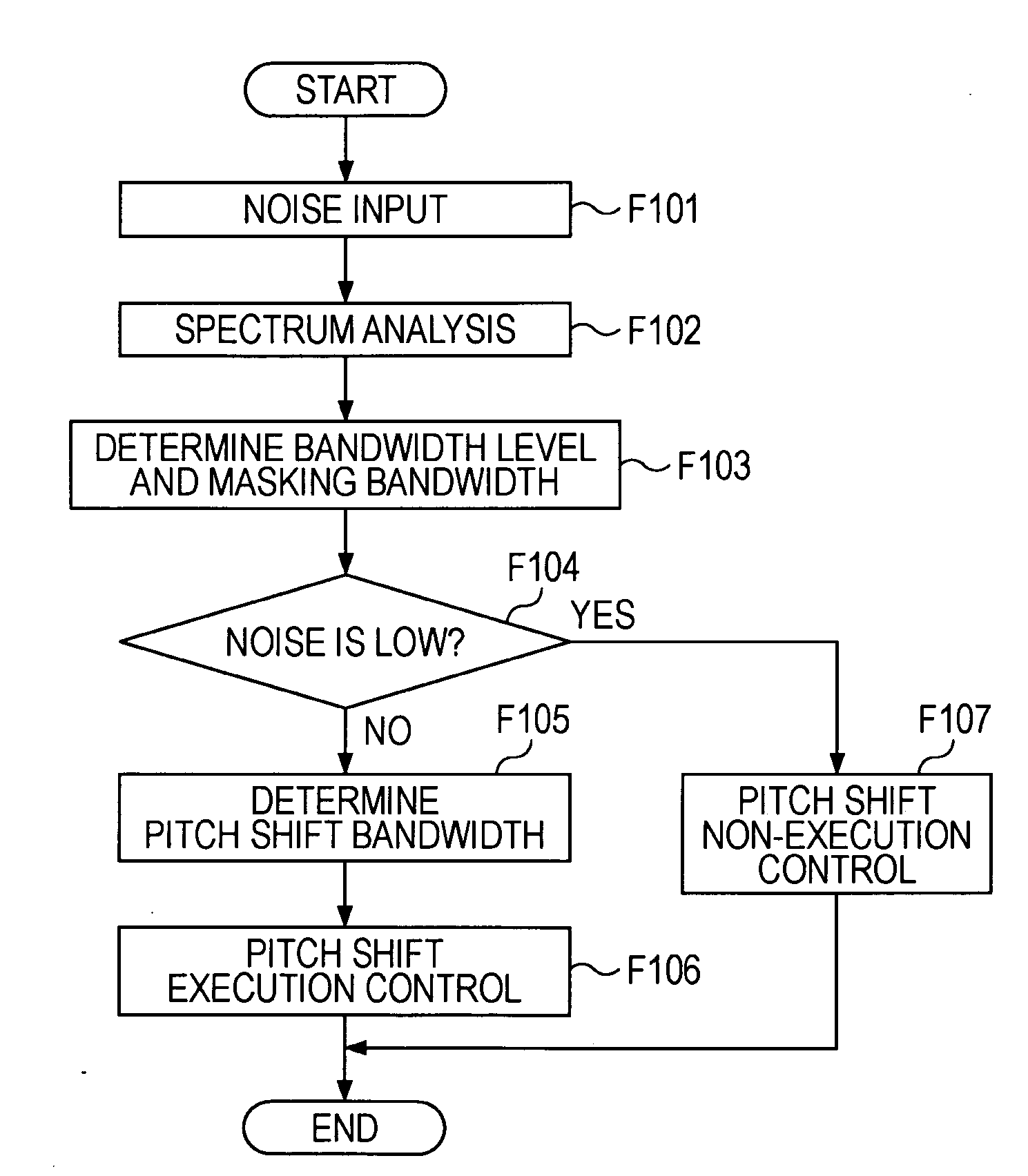
[0040]The spectrum analysis / control unit 4 performs spectrum analysis of the input noise audio signal and detects the level of each frequency band. As described below, the spectrum analysis / control unit 4 also controls the operation of the band dividing unit 6 and the pitch shift unit 7 in accordance with the de...

second embodiment

[0111]The configuration of an audio apparatus 1 according to a second embodiment is illustrated in FIG. 7. The components that are same as those in FIG. 1 will be indicated by the same reference numerals, and descriptions thereof will not be repeated.

[0112]In such a case, an audio signal SA1 from an audio reproduction unit 5 is directly supplied to a combining unit 8 and is supplied to a bandpass tunable filter unit 11.

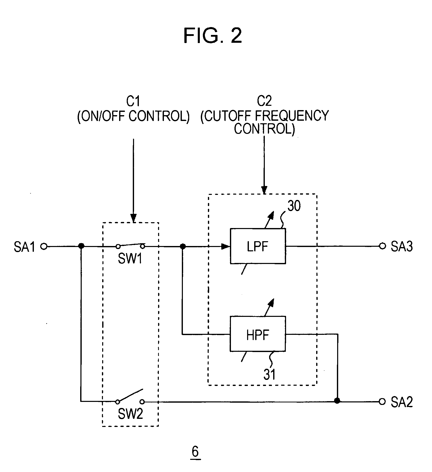
[0113]The bandpass tunable filter unit 11 includes, for example, a switch SW1 and a bandpass tunable LPF 30, as shown in FIG. 8. The switch SW1 is turn on or off by a control signal C1 from a spectrum analysis / control unit 4. The cutoff frequency of the bandpass tunable LPF 30 is variably set by a control signal C2 from the spectrum analysis / control unit 4.

[0114]The output from the bandpass tunable LPF 30 is supplied to a pitch shift unit 7 as an audio signal SA3 of a frequency band subjected to a pitch shifting.

[0115]At the pitch shift unit 7, a pitch shift signal SA...

third embodiment

[0126]A third embodiment will be described with reference to FIG. 9. The components that are the same as those in FIG. 1 will be represented by the same reference numerals, and descriptions thereof will not be repeated.

[0127]The configuration illustrated in FIG. 9 is the same as that illustrated in FIG. 1, except that a low-band noise detection / control unit 14 is provided instead of the spectrum analysis / control unit 4. The low-band noise detection / control unit 14 is a section that performs simple spectral analysis. The low-band noise detection / control unit 14 extracts only the low frequency band of the noise audio signal collected at a microphone 2 using an LPF having a cutoff frequency of a specific frequency fx and detects the noise level of the extracted frequency band. Then, the low-band noise detection / control unit 14 determines whether or not masking has occurred according to the detected noise level.

[0128]An audio signal SA1 from an audio reproduction unit 5 is supplied to a...


PUM


Abstract

An audio output apparatus includes a masking band determining unit configured to determine a first frequency band in which masking due to environmental sounds is likely to occur in audio signal output sounds; a band-component extracting unit configured to extract a signal component from an input audio signal in the first frequency band determined by the masking band determining unit; a pitch shift unit configured to perform pitch shifting of the signal component in the first frequency band extracted by the band-component extracting unit and generate a pitch shift signal containing a signal component of at least a doubled frequency; and a signal output unit configured to supply an audio signal containing the pitch shift signal acquired by the pitch shift unit to a connected speaker.

Description

CROSS REFERENCES TO RELATED APPLICATIONS[0001]The present invention contains subject matter related to Japanese Patent Application JP 2008-044822 filed in the Japanese Patent Office on Feb. 26, 2008, the entire contents of which are incorporated herein by reference.BACKGROUND OF THE INVENTION[0002]1. Field of the Invention[0003]The present invention relates to an audio output apparatus and an audio output method particularly suitable for use in an environment with high levels of exogenous noise.[0004]2. Description of the Related Art[0005]In environments with high levels of exogenous noise, such as inside an automobile, it is often difficult to music and so on.[0006]FIG. 10 illustrates an example in which the noise level inside a traveling automobile is measured. As shown in the drawing, noise having a high level in a low frequency band is generated in a traveling automobile.[0007]When listening to music and so on with an in-vehicle audio system, in particular, low frequencies of th...

Claims


Application Information

Patent Timeline
IPC IPC(8): H04R3/02
CPCH04R2499/13H04R3/04
Inventor SAWASHI, TOKIHIKO
Owner SONY CORP
Why Eureka
Try Eureka