

Water level & temperature indicator
a technology of water level and temperature indicator, which is applied in the field of signal alarm, can solve the problems of inability to disperse water, waste of water flowing longer than needed, and limited capacity of overflow, and achieves the effect of less invasive to the bathtub, convenient float to inner float chamber clearance, and quick and easy float chang
- Summary
- Abstract
- Description
- Claims
- Application Information
AI Technical Summary
Benefits of technology
Problems solved by technology
Method used
Image

Examples
Embodiment Construction
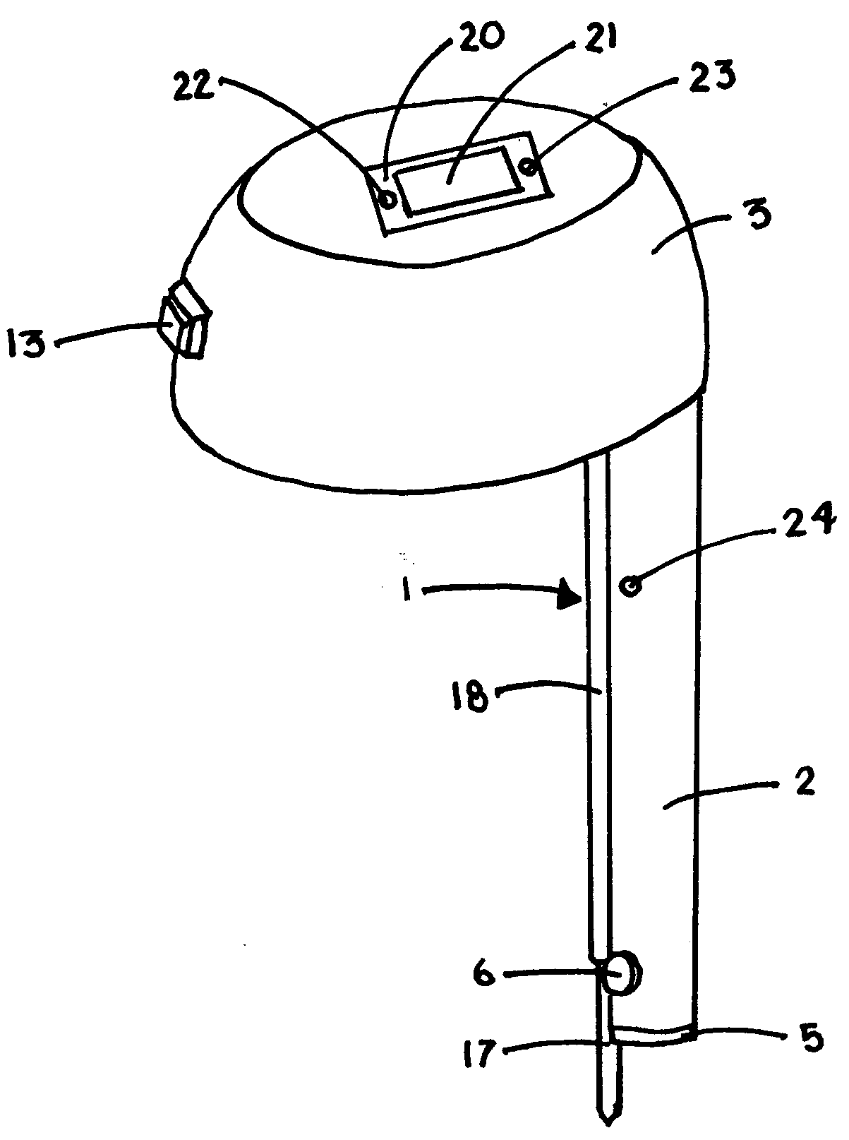
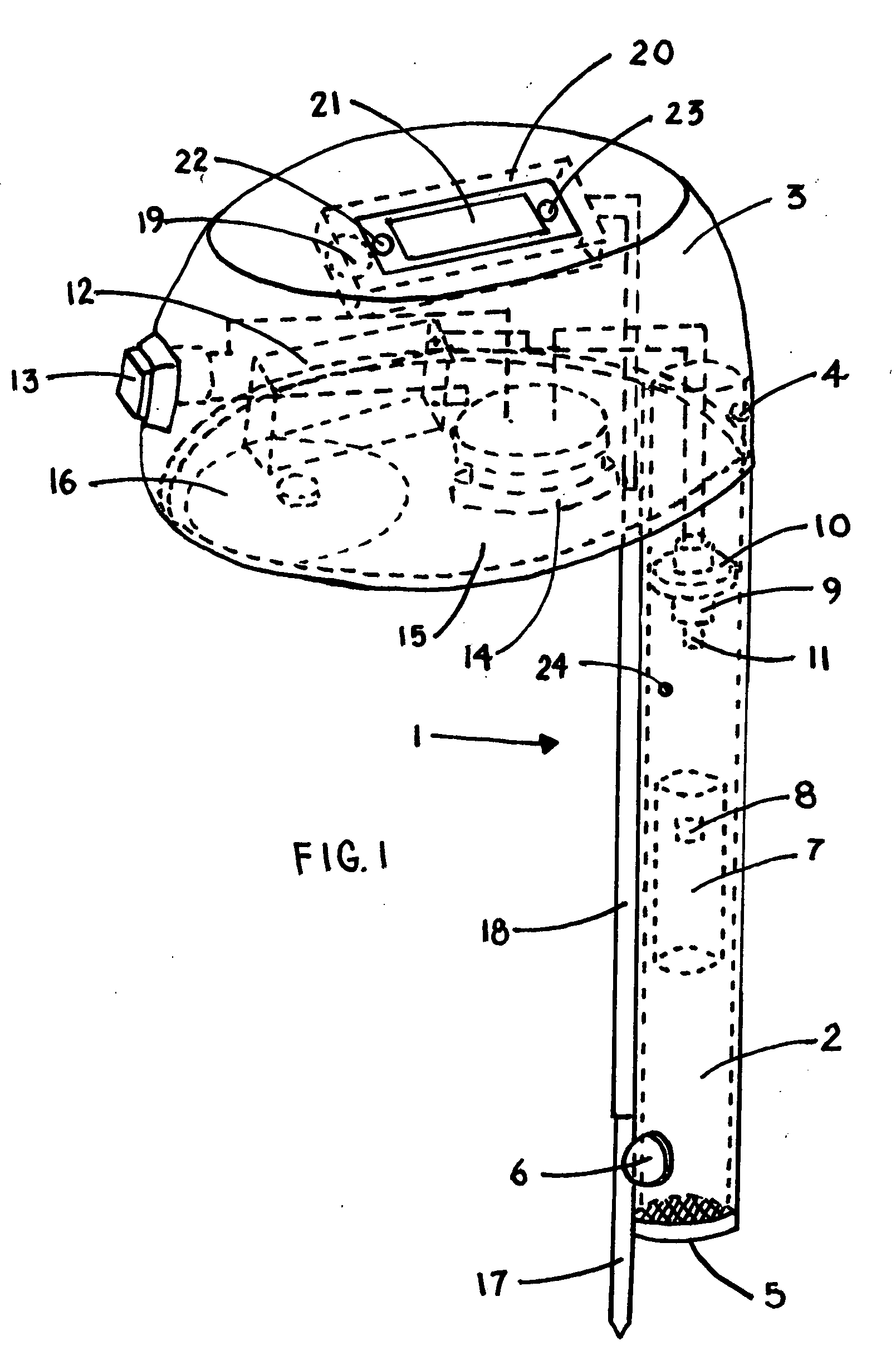
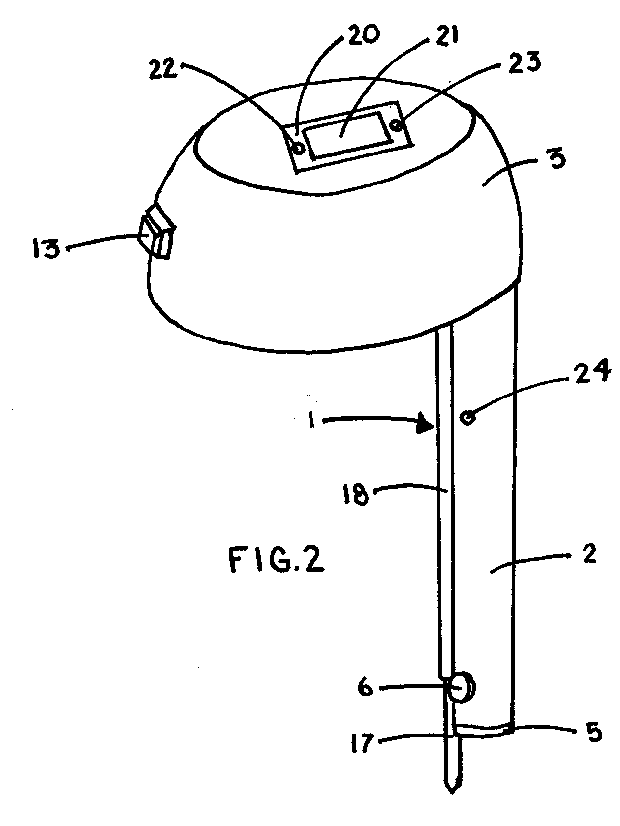
[0002]Referring now to the views of the drawing, it will be noted that the water level and temperature indicating device 1 comprises a hood unit 3 carrying a laterally extended cylindrical tube member 2 at one end. Both units are primarily made of a suitable metal or plastic material and are connected together by suitable fasteners 4 or a spot weld 4.
[0003]Member 2 is hollow and is open at the bottom end with the exception of a removable screen unit 5 which is press fitted into the member 2. The screen unit is comprised of a screen of suitable material imbedded in a flexible plastic or rubber casting. A rubber bumper 6 is fixed to the lower side of member 2 with double sided tape or other suitable adhesive. Member 2 contains a cylindrically shaped float unit 7 which is primarily made from Styrofoam or cork. This float contains a small weight 8 made of stainless steel or suitable material. Member 2 also contains a modified, push on switch 9. This switch 9 is mounted inside the upper ...
PUM
 Abstract
Description
Claims
Application Information