Fuel cell cooling system

a technology of fuel cell and cooling system, which is applied in the direction of fuel cells, electrical equipment, electrochemical generators, etc., can solve the problems of conventional cooling system described above, power generation cells are overheated, and cannot generate power, so as to reduce the temperature of the cooling system and reduce the heat resistance. , the effect of increasing the selection range of ion-exchange resins

Inactive Publication Date: 2009-12-24
TOYOTA BOSHOKU KK
View PDF5 Cites 21 Cited by
  • Summary
  • Abstract
  • Description
  • Claims
  • Application Information

AI Technical Summary

Benefits of technology

[0016]In the present invention, the heated coolant having a high temperature after having been used for cooling the fuel cell, is cooled by the cooler before or after entering inside the ion exchanger, and then the coolant has a low temperature. Since an operating temperature of the ion-exchange resins is lowed, ion-exchange resins having a low heat resistant temperature can be used. In addition, even when the operating temperature is set high for the cooling system as a whole, the ion-exchange resins are cooled by the cooler to a predetermined temperature, and thus a maximum value of a heat resistant temperature of the ion-exchange resins can be set high. Moreover, an allowable temperature range of the cooli

Problems solved by technology

Without heat dissipation, the power generation cells are overheated and unable to generate power.
However, the conventional cooling system described above has problems.
In addition, since it is required to take into account the heat resistant temperature of the ion-exchange resins, an operating temperature of t

Method used


Image

  • Fuel cell cooling system
  • Fuel cell cooling system
  • Fuel cell cooling system

Examples


Embodiment Construction

[0026]The particulars shown herein are by way of example and for purposes of illustrative discussion of the embodiments of the present invention only and are presented in the cause of providing what is believed to be the most useful and readily understood description of the principles and conceptual aspects of the present invention. In this regard, no attempt is made to show structural details of the present invention in more detail than is necessary for the fundamental understanding of the present invention, the description is taken with the drawings making apparent to those skilled in the art how the forms of the present invention may be embodied in practice.

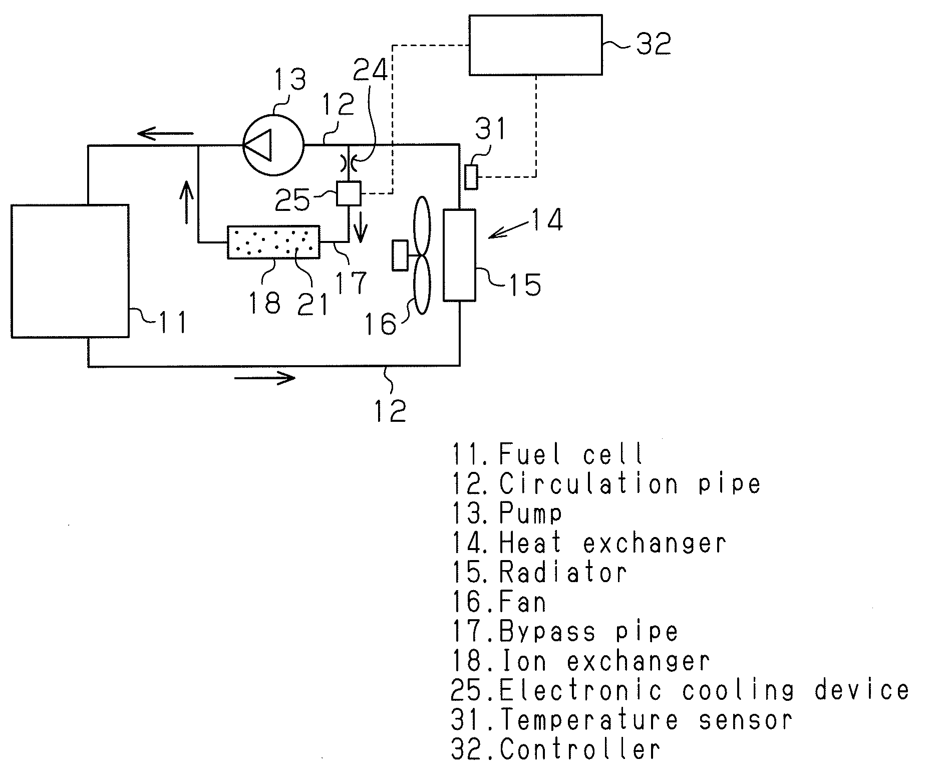
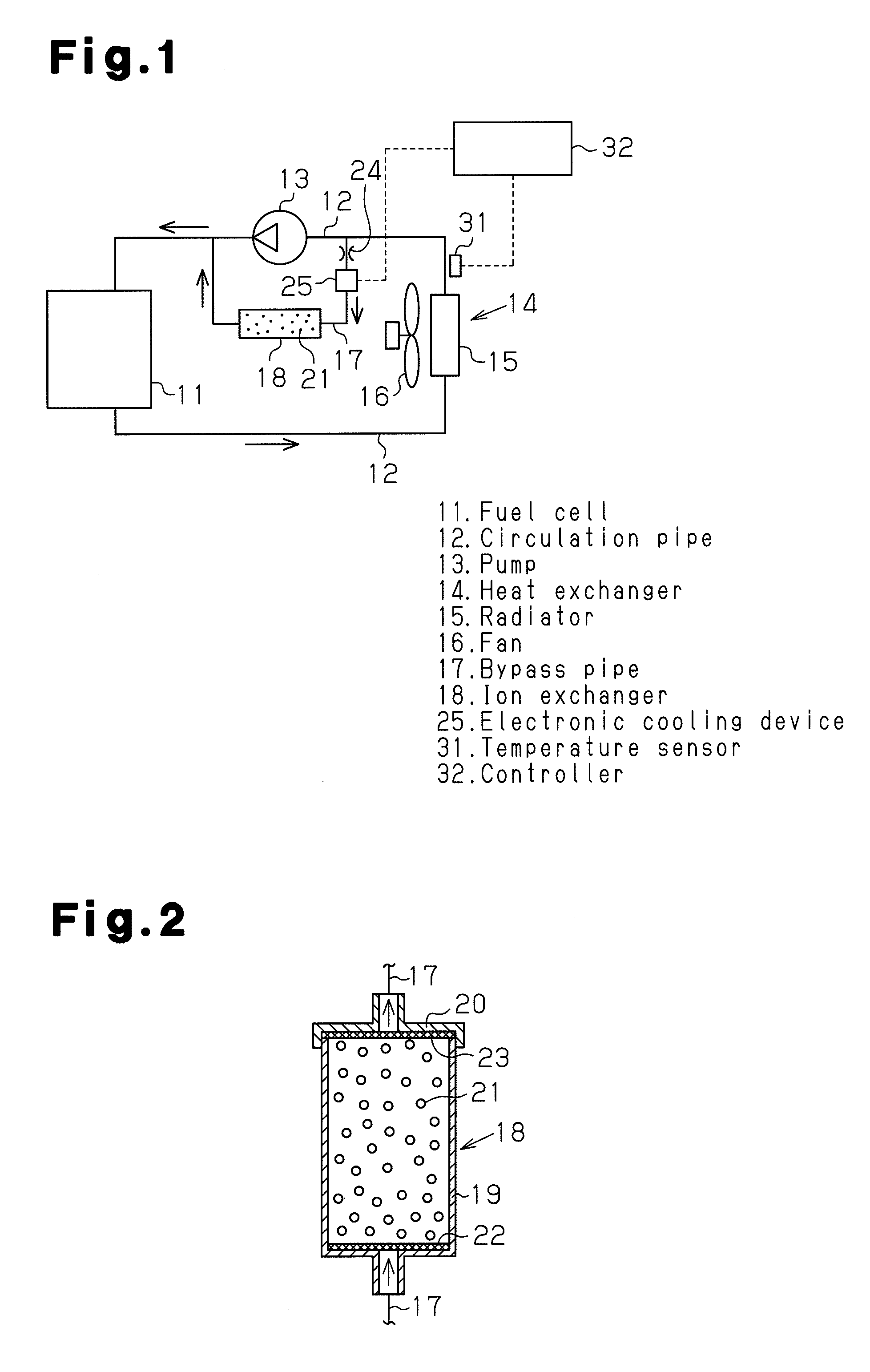
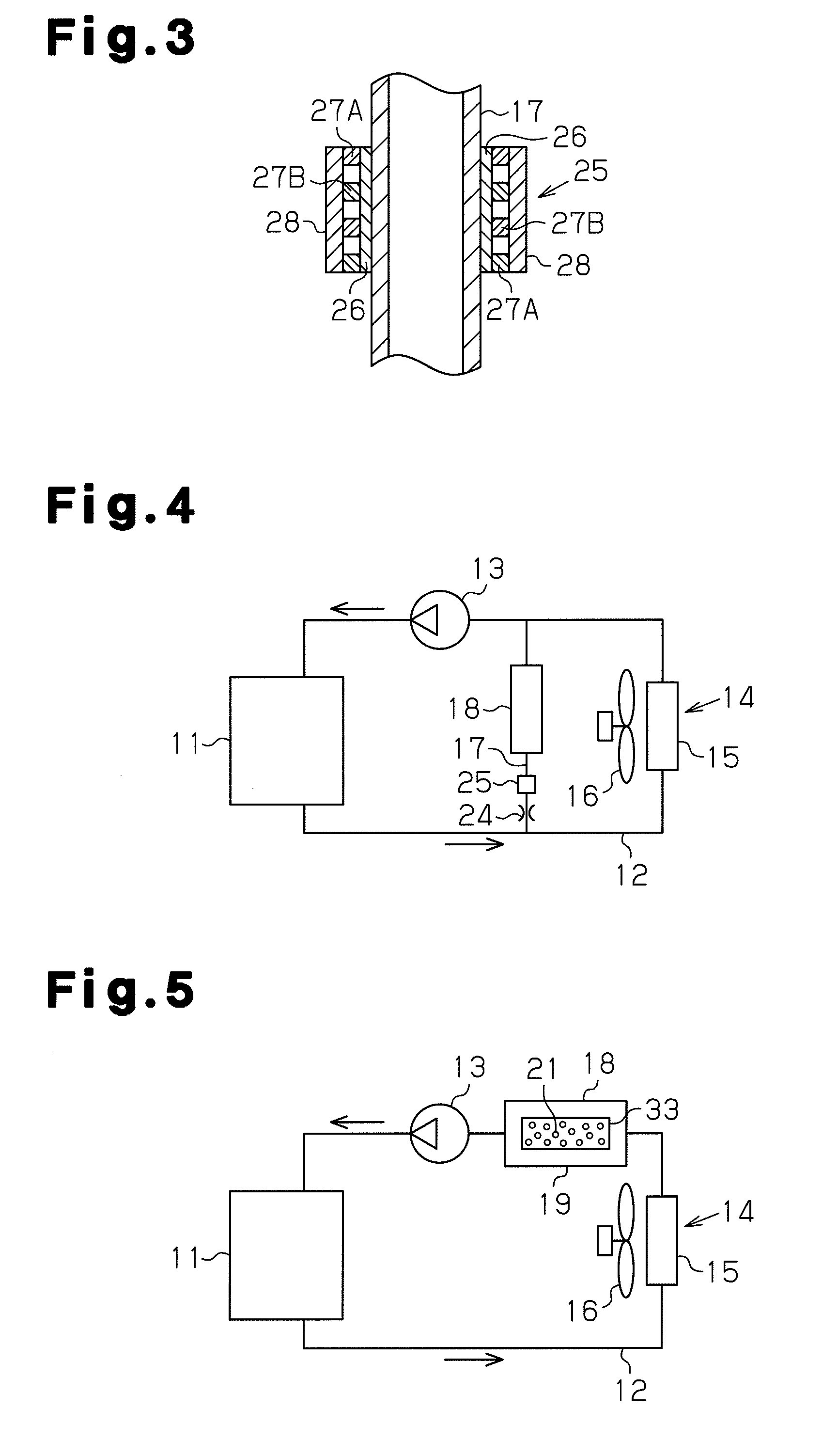
[0027]An embodiment, in which the present invention is embodied as a cooling system of a fuel cell for an electric vehicle, is explained below with reference to FIGS. 1 to 3. A fuel cell 11 is internally provided with a fuel pole, an oxidant pole, and numerous layered power generation cells, which are composed of solid electro...


PUM


Abstract

A circulation pipe for a coolant is connected to a fuel cell. A pump and a heat exchanger are connected to the circulation pipe. A bypass pipe is connected in parallel with the pump. An ion exchanger is connected to the bypass pipe. An electronic cooling device is connected to the bypass pipe on an upstream side of the ion exchanger. The coolant, which is supplied to the ion exchanger, is cooled by the electronic cooling device to a predetermined temperature, so that the ion-exchange resins are prevented from being abnormally heated by the coolant.

Description

CROSS-REFERENCE TO RELATED APPLICATIONS[0001]The present application claims priority under 35 U.S.C. §119 of Japanese Application No. 2008-159190 filed on Jun. 18, 2008, the disclosure of which is expressly incorporated by reference herein in its entirety.BACKGROUND OF THE INVENTION[0002]1. Field of the Invention[0003]The present invention relates to a fuel cell cooling system, more specifically to a cooling system that performs cooling by absorbing heat by heat exchange, the heat being generated from power generation cells when a fuel cell generates power.[0004]2. Description of Related Art[0005]In a fuel cell system, when numerous power generation cells layered in the fuel cell generate power as hydrogen gas and oxygen gas react to each other, the power generation cells generate heat. Without heat dissipation, the power generation cells are overheated and unable to generate power. In order to cool the power generation cells when power is generated, a coolant cooling system is gene...

Claims


Application Information

Patent Timeline
IPC IPC(8): H01M8/04
CPCH01M8/04029H01M8/04044Y02E60/50H01M8/04417H01M8/04768H01M8/04358
Inventor IMAMURA, ATSUSHIMORITA, AKISHI
Owner TOYOTA BOSHOKU KK
Why Eureka
Try Eureka