Vascular graft connector

a technology of vascular grafts and connectors, which is applied in the field of prosthetic vascular connectors, can solve the problems of serious caution in observation and treatment after surgery, death by any kind of negligence, and risky cardiac surgery

Inactive Publication Date: 2010-02-11
KANG WEI CHANG +1
View PDF1 Cites 12 Cited by
  • Summary
  • Abstract
  • Description
  • Claims
  • Application Information

AI Technical Summary

Benefits of technology

[0010]The objective of the present invention is to provide a prosthetic vascular connector which features concise in architecture, handy in operation, and stable in connection, and no biocompatibility as well.

Problems solved by technology

The cardiac surgery was for sure risky while the suture of large-vessel by the end of surgery was even more crucial.
Even if the surgery is operated smoothly, the observation and treatment after the surgery demand serious caution.
It could be fatal to life by any sort of negligence.
This step is hard to operate, and it takes carefulness and patience to accomplish.
The success of this capping often requires many times of efforts which deteriorates this joining operation.
Once a conventional prosthetic vascular connector works for the connection, the flowing blood will keep contacting the internal surface of the inner ring, which causes thrombus effects along the internal surface of the inner ring after a lengthy use, which in turn brings about embolism to the remote blood vessel, causing potential troubles of further processing which again deteriorates the operation.

Method used


Image

  • Vascular graft connector
  • Vascular graft connector
  • Vascular graft connector

Examples


Embodiment Construction

[0018]To achieve the foregoing objects of the present invention, the techniques adopted and the achievable fuction are detailed described with reference to the following preferred exemplified embodiments and the accompanying drawings, which is expected to help those skilled in the art to comprehend the present invention thoroughly.

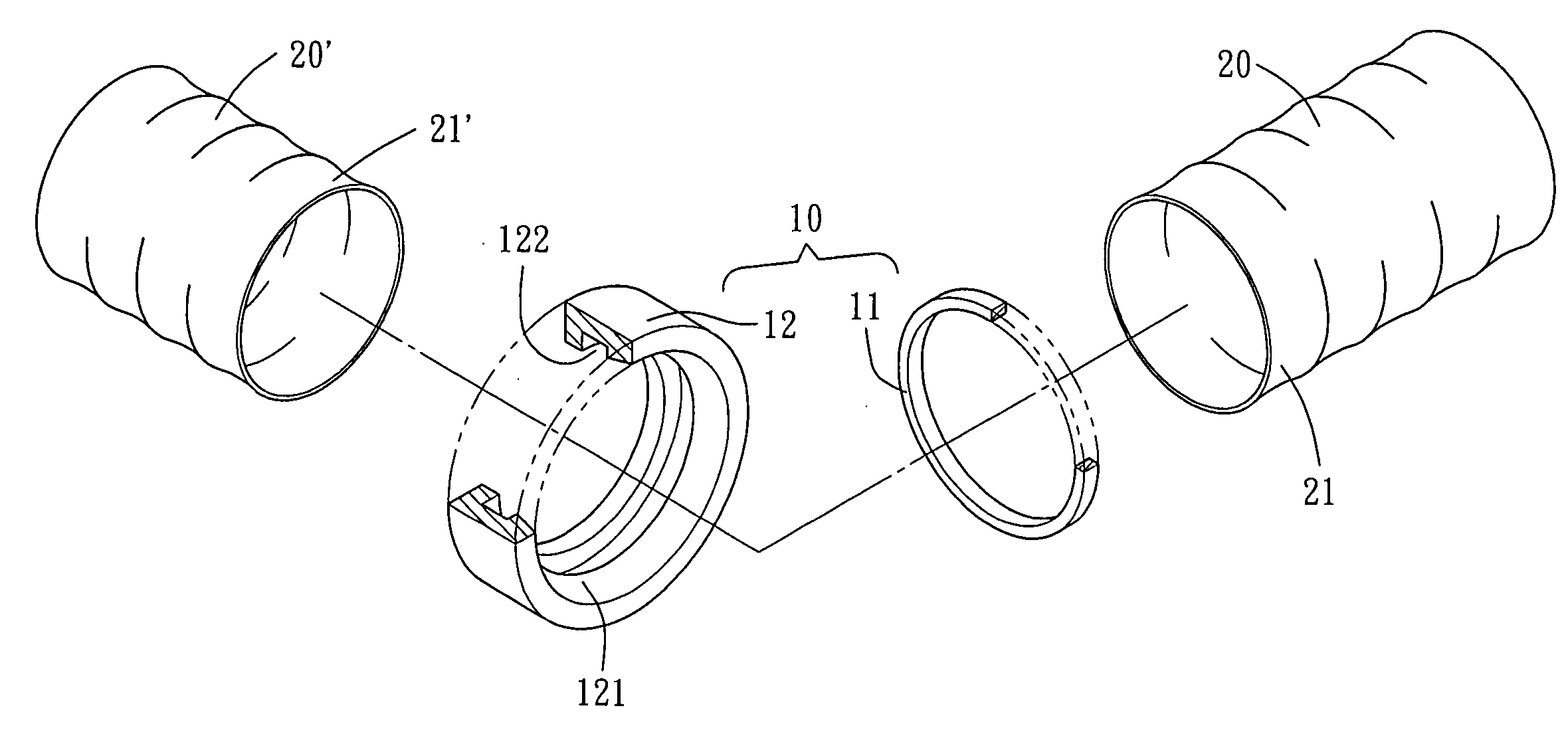
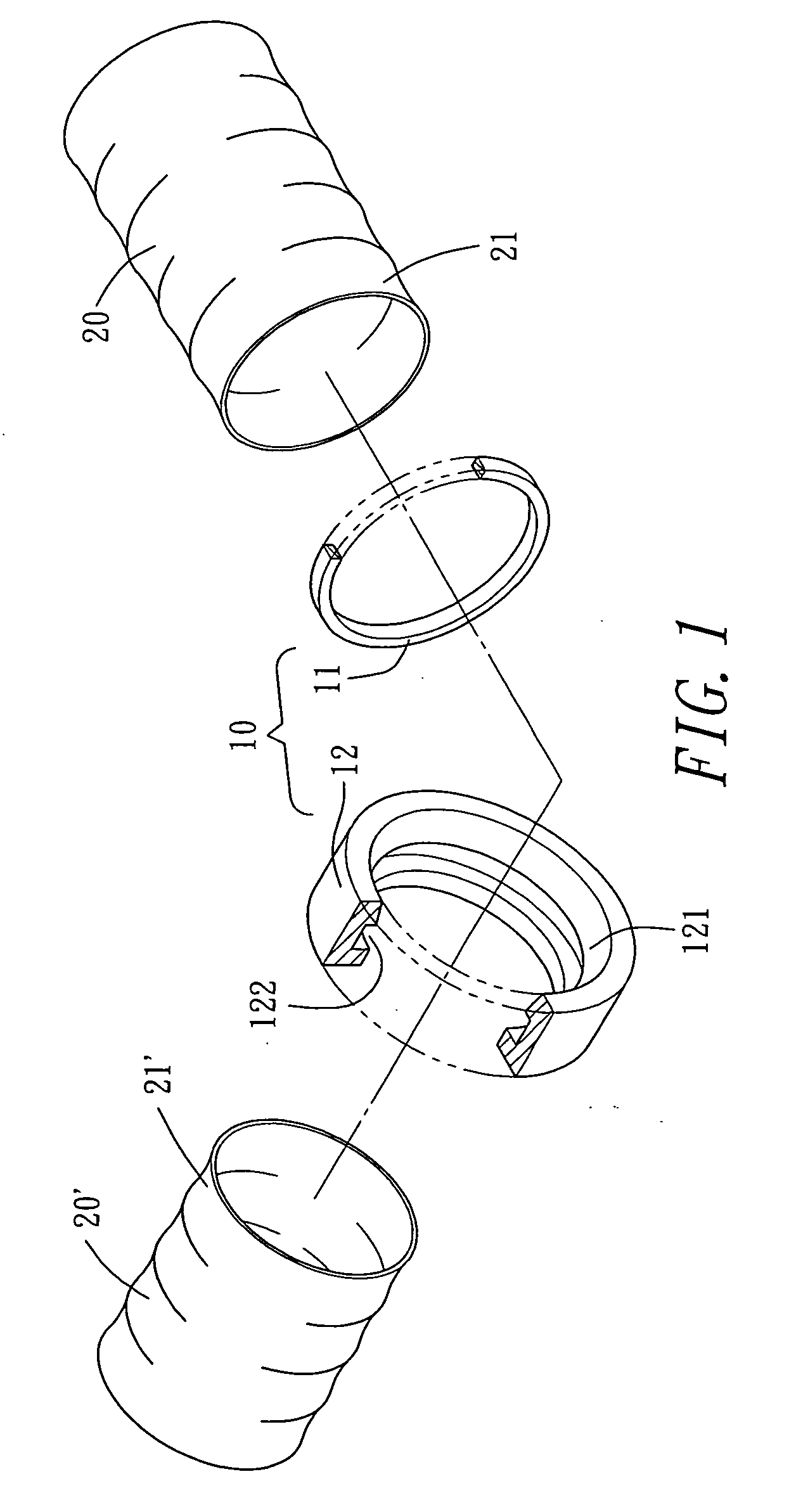
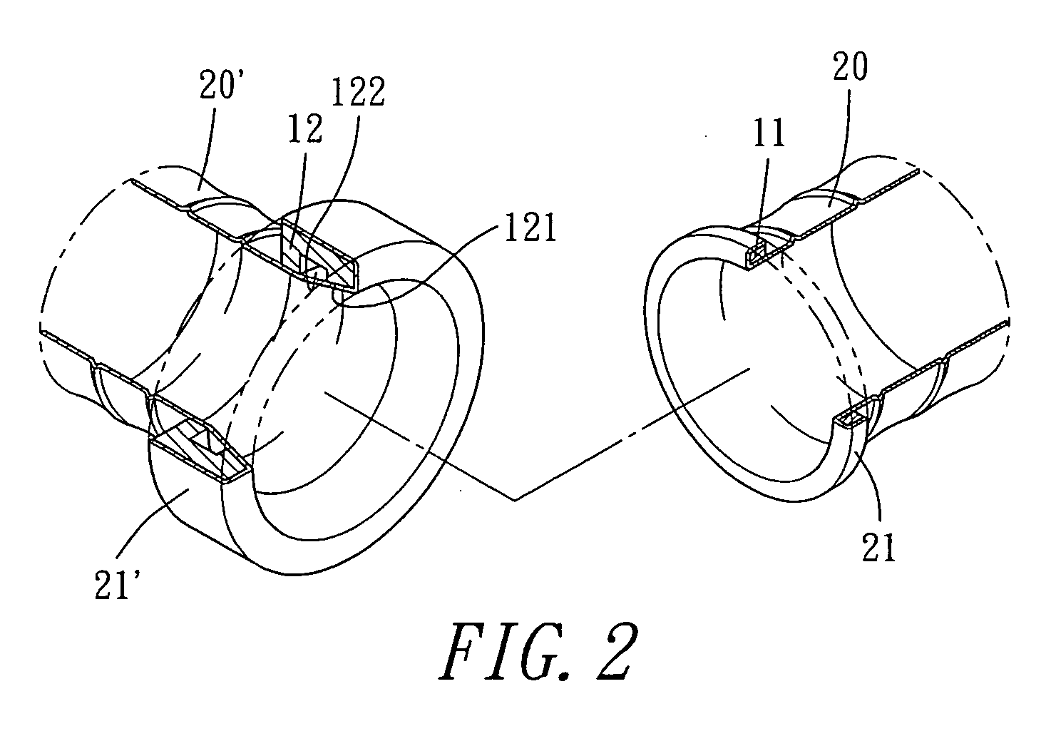
[0019]Referring to FIG. 1, the first exemplified embodiment of the present invention is a connector 10, which is used to join the terminal portions 21, 21′ of the two prosthetic blood vessels 20, 20′. The connector 10 is divided architecturally into two components: a male fastener 11 and a female fastener 12, where the male fastener 11 is a ring-shaped body with a inner diameter same as the diameter of the cross section of the terminal portion 21 of a first prosthetic blood vessel 20, which is handy to take the terminal portion 21 of a first prosthetic blood vessel 20 to pass through the inside of the male fastener 11 followed by a reverse fold shown in FI...


PUM


Abstract

The present invention is to provide a prosthetic vascular connector which comprises a male fastener of ring-shaped body and a ring-shaped female fastener; where the outer side of the female fastener is a smooth surface while the inner side, facing the male fastener, is provided with a tapered wall that is gradually contracted inward and an indented catch trough next to the minimum diameter of the tapered wall; when in use, the male fastener and the female fastener each offers the terminal portion of a separate prosthetic blood vessel to pass through its inside, followed by a outward to backward fold around it, and then push the male fastener with the folded terminal portion of the prosthetic blood vessel into the tapered wall of the female fastener covered with the prosthetic blood vessel, where the male fastener is being pushed into a deformed shape to move across the minimum diameter of the tapered wall of the female fastener, and lodged in the catch trough with its original shape restored.

Description

BACKGROUND OF THE INVENTION[0001]1. Field of the Invention[0002]The present invention relates to prosthetic vascular connectors, more particularly, to one formed by a male fastener and a female fastener, where each offers the terminal portion of a prosthetic blood vessel a penetration through it's inside, followed by an outward to backward fold around it for fastening; the connector features advantages as concise in structure, handy in operation and firm in connection; moreover, there is no contact with the flowing blood for the connector that absolutely avoids thrombus.[0003]2. Description of the Prior Art[0004]The progress of the medical science brings about an abundance of new pharmaceuticals and medical equipment, which prolongs the age of modern human beings considerably. Moreover, the credits are also given to the considerable advancement of expertise of the medical profession and technician. People in the early days realized they were confronted with critical moment of their ...

Claims


Application Information

Patent Timeline
Patent Type & Authority Applications(United States)
IPC IPC(8): A61B17/08
CPCA61B17/11A61F2/064A61B2017/1132A61B2017/1107
Inventor KANG, WEI-CHANGKANG, YU-LI
Owner KANG WEI CHANG
Why Eureka
Try Eureka