Induction system for internal combustion engine

a technology of induction system and internal combustion engine, which is applied in the direction of combustion engine/fuel air treatment, machines/engines, mechanical equipment, etc., can solve the problems of not being able to achieve the desirable characteristic of heat release in the induction system, and the engine compartment of a vehicle is a large amount of heat to be released, and achieve excellent mixing of exhaust gas and high efficiency

Active Publication Date: 2010-03-18
FORD GLOBAL TECH LLC
View PDF21 Cites 4 Cited by
  • Summary
  • Abstract
  • Description
  • Claims
  • Application Information

AI Technical Summary

Benefits of technology

[0013]It is an advantage of an engine having an induction system according to the present invention that high efficiency may be achieved with a turbocharger, but without excessive rejection of heat to the environment immediately surrounding the engine.
[0014]It is yet another advantage of an induction system according to the present invention that a Vee-block engine may be produced in a much more compact fashion.
[0015]It is another advantage of an engine having an induction system according to the present invention that the length of the induction system provides an opportunity for excellent mixing of exhaust gas, in the form of exhaust gas recirculation, in the incoming air charge.

Problems solved by technology

This causes a great deal of heat to be released to the engine compartment of a vehicle, and such heat release is certainly not a desirable characteristic of an induction system.

Method used


Image

  • Induction system for internal combustion engine
  • Induction system for internal combustion engine
  • Induction system for internal combustion engine

Examples


Embodiment Construction

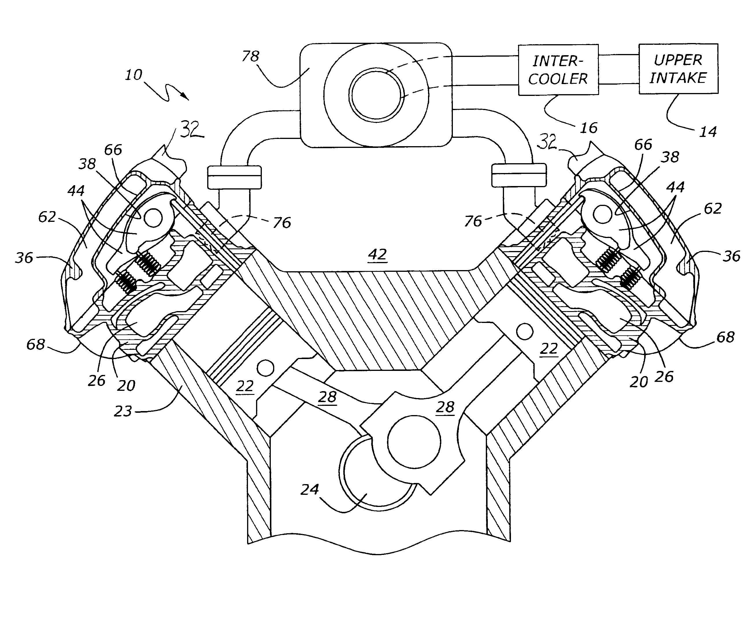
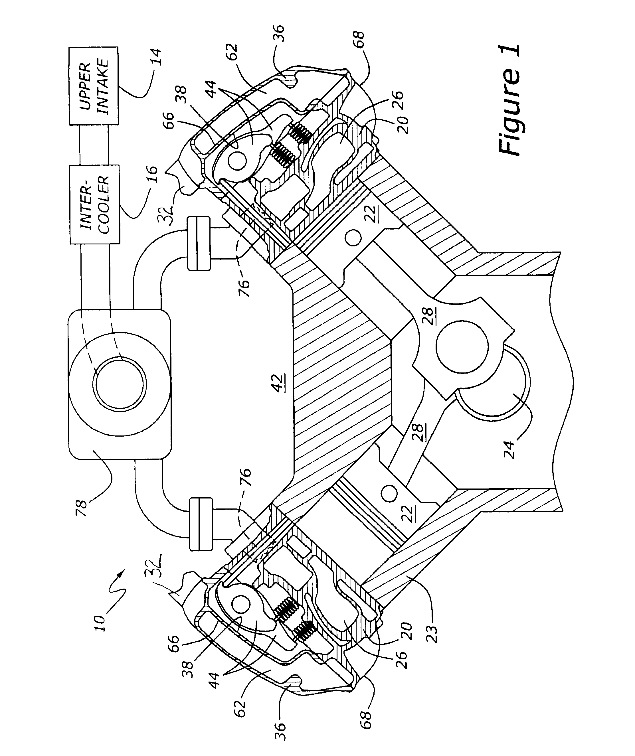
[0021]As shown in FIG. 1, engine 10 has a cylinder block, 23, housing a crankshaft, 24, and multiple pistons, 22, which are mounted to crankshaft 24 by connecting rods 28. Two cylinder heads, 20, are shown as being mounted upon cylinder block 23. Taken together, cylinder heads 20 and cylinder block 23 define a valley area, 42, which is occupied in part by a turbocharger, 78, which is connected with an intercooler, 16, and an upper intake, 14. FIG. 1 also shows intake runners, 62, which are part of a lower intake, 32. Intake runners 62 conduct air flowing from turbocharger 78 and through intercooler 16 and upper intake 14 to intake ports, 26, which are formed within cylinder heads 20.

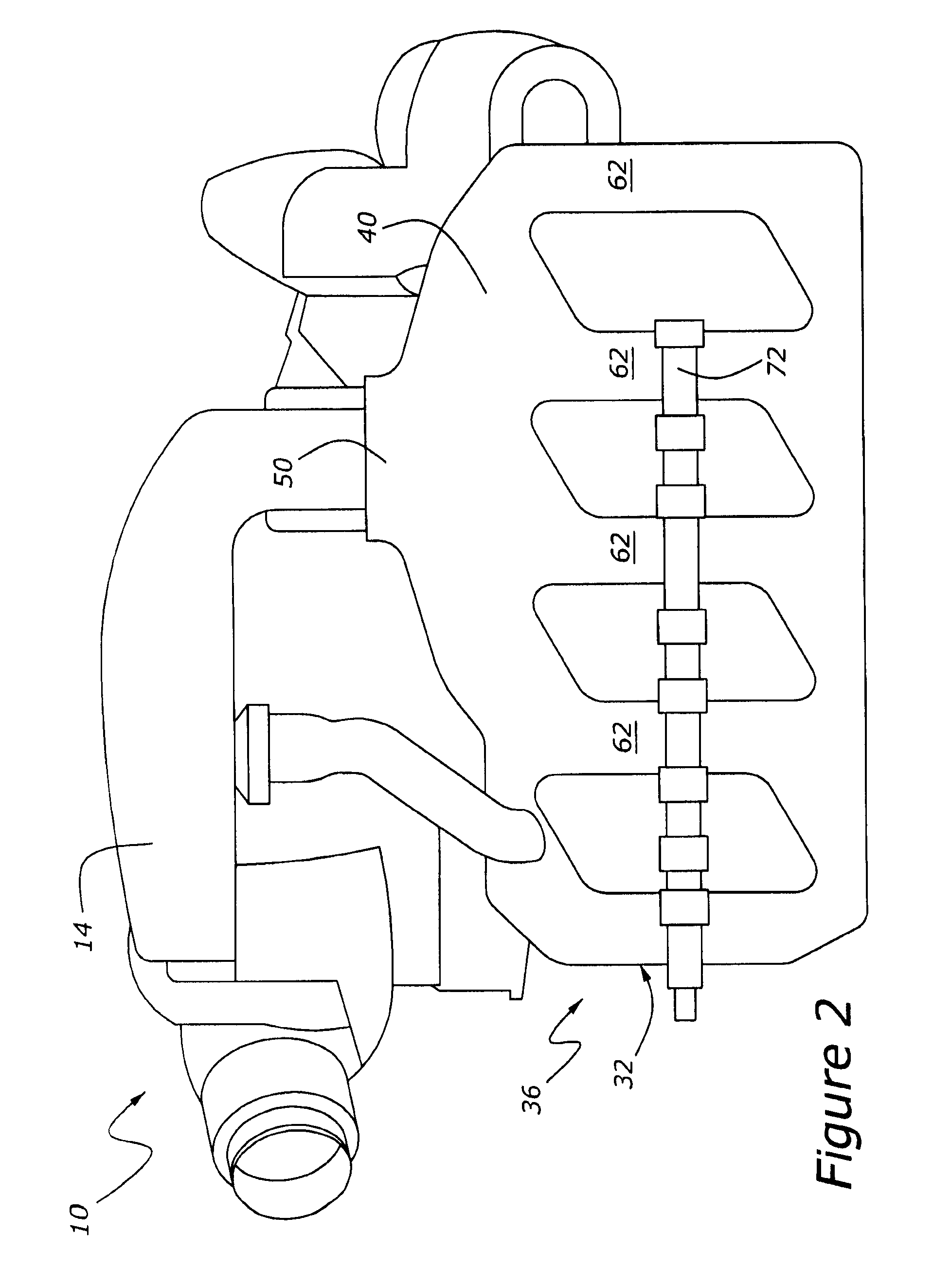
[0022]FIGS. 2 and 3 show details of upper intake 14 and lower intake 32. Lower intake 32 begins with a plenum, 50, which is connected with a number of intake runners, 62 (see also FIG. 1). Plenum 50, which is configured as an open plenum, is centrally located and receives air from an upper intake, 14. Pl...


PUM


Abstract

An induction system for an internal combustion engine includes an upper intake for receiving air from a supply, such as a turbocharger, and a lower intake which combines a cylinder valve actuator cover, a plenum for receiving air from the upper intake, and a number of intake runners which extend across, an integrally with, the cylinder valve actuator cover to cylinder head intake ports which are configured at outboard sides of the engine cylinder head.

Description

CROSS REFERENCE TO RELATED APPLICATIONS[0001]None.BACKGROUND OF THE INVENTION[0002]1. Field of the Invention[0003]The present invention relates to an internal combustion engine having inboard exhaust ports and outboard intake ports located within cylinder heads. The engine also has a lower intake functioning not only as an intake but, also, as a valve actuator cover.[0004]2. Related Art[0005]Internal combustion engine induction systems have become increasingly more sophisticated during the last few decades as a result of the need for improved fuel economy and lower emissions. Particularly in the case of compression ignition engines, turbocharging has risen to the fore. Efficient turbocharging demands that exhaust gases be collected and conducted through the exhaust turbine portion of the turbocharger, which must be matched with a compressor portion providing fresh air charge to the engine cylinders. In the case of a turbocharged Vee-block engine, the task of routing the exhaust and ...

Claims


Application Information

Patent Timeline
Patent Type & Authority Applications(United States)
IPC IPC(8): F02M35/104
CPCF02M35/10052Y02T10/146F02M35/116Y02T10/12
Inventor CURRIE, DAVIDLAZICH, IVAN
Owner FORD GLOBAL TECH LLC
Why Eureka
Try Eureka