Charging fluid intake module and internal combustion engine

a technology of internal combustion engine and charging fluid, which is applied in the direction of combustion air/fuel air treatment, machines/engines, mechanical equipment, etc., to achieve the effect of improving the performance capability and improving the performance of the exhaust gas recirculation system

Active Publication Date: 2010-04-01
BEHR GMBH & CO KG
View PDF10 Cites 29 Cited by
  • Summary
  • Abstract
  • Description
  • Claims
  • Application Information

AI Technical Summary

Benefits of technology

[0011]It is therefore an object of the present invention to improve the performance of an exhaust gas recirculation system, whereby a device is provided that permits a space-saving design and improved performance capability in an exhaust gas recirculation system.

Problems solved by technology

In this context, it was noted that it can be disadvantageous to supply an exhaust gas ahead of the heat exchanger, since in such a case the scavenging drop is additionally reduced by the pressure drop on the charging fluid side, which to say on the air side, of the heat exchanger provided for the gaseous charging fluid, in particular for charge air.

Method used


Image

  • Charging fluid intake module and internal combustion engine
  • Charging fluid intake module and internal combustion engine
  • Charging fluid intake module and internal combustion engine

Examples


Embodiment Construction

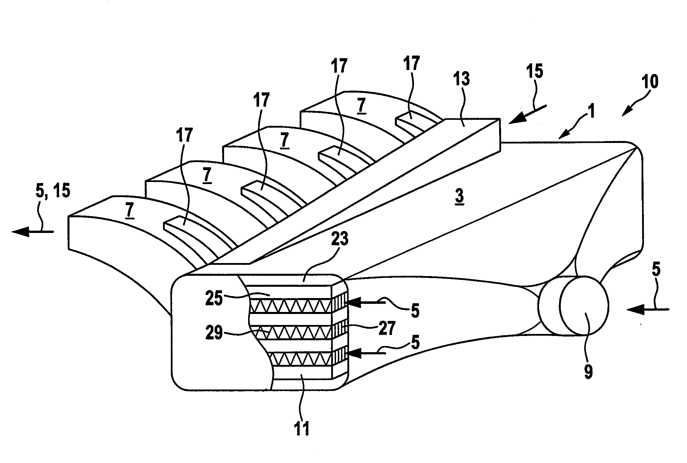
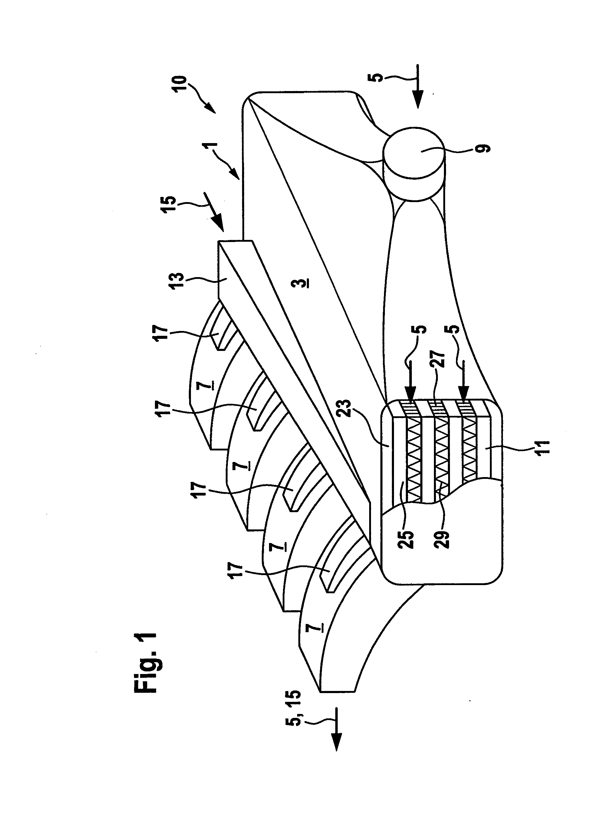
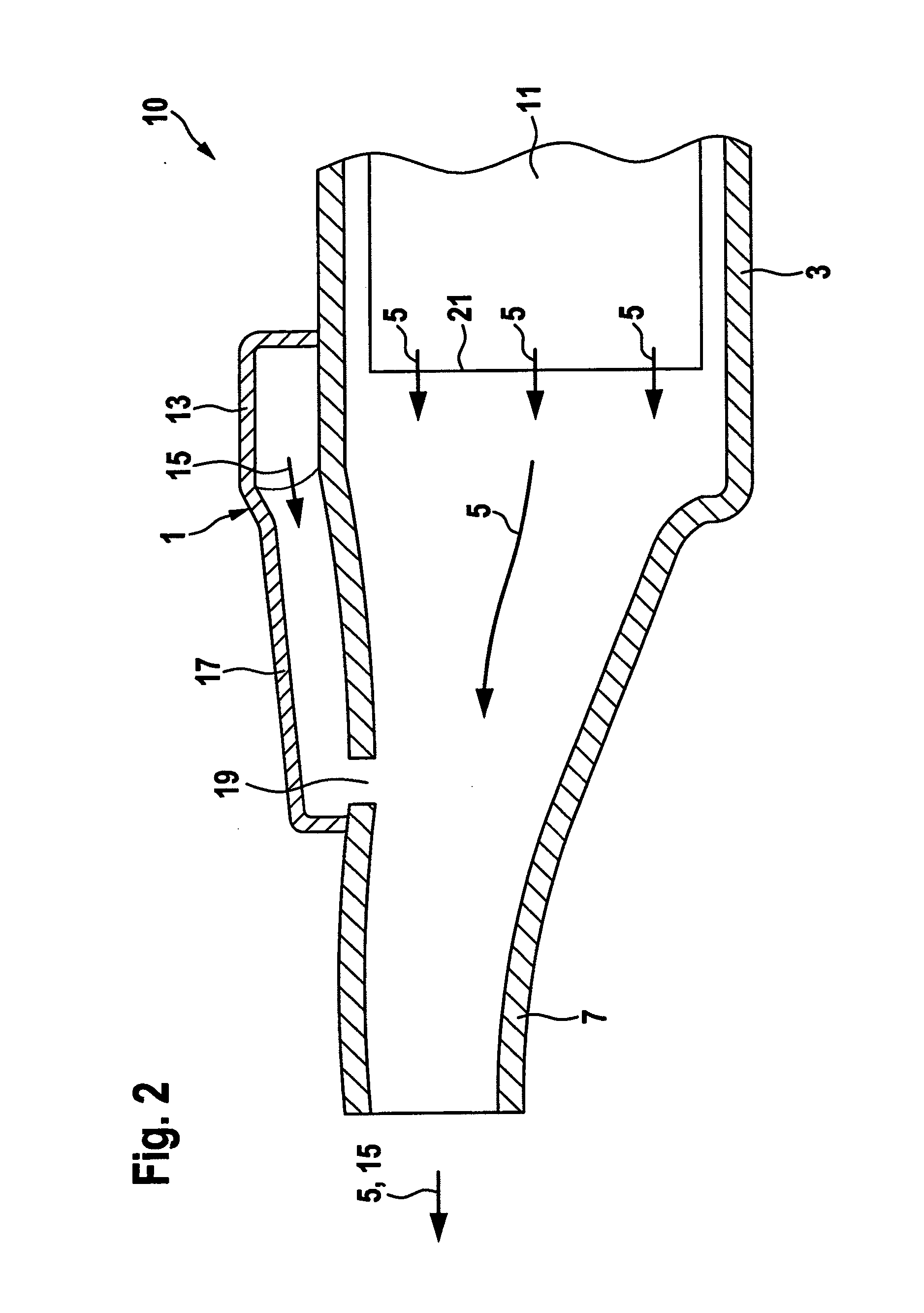
[0038]FIG. 1 shows a charging fluid intake module in the form of a charge air module or air intake module 10 for an internal combustion engine (not shown in detail) according to a first preferred embodiment of the invention. The air intake module 10 shown in cross-section in FIG. 2 has, as part of a housing 1, an intake plenum 3 for a charging fluid in the form of charge air 5, and a number of individual intake ports 7 associated with cylinders (not shown in detail) of the internal combustion engine, which are also known as intake manifolds. The charge air 5 is supplied to the cylinders of the internal combustion engine by means of the intake manifolds. The flow path of the charge air 5, indicated by arrows by way of example, in the housing 1 leads on the intake side from an intake fitting, which is not shown in detail, through a schematically shown throttle valve 9 into the intake plenum 3, through the schematically shown integrated heat exchanger in the form of an intercooler 11 i...


PUM

PropertyMeasurementUnit
sizesaaaaaaaaaa
shapesaaaaaaaaaa
pressureaaaaaaaaaa

Abstract

A charging fluid suctions module is provided for an internal combustion engine, comprising a housing forming a flow path for a gaseous charging fluid, particularly air, a gas, and / or an air / gas mixture. Whereby, a heat exchanger is disposed in the housing for the gaseous charging fluid. In order to allow for an improved exhaust gas return the housing comprise an inlet channel for an exhaust gas, and the inlet channel flows into the flow path downstream of the heat exchanger for the gaseous charging fluid.

Description

[0001]This nonprovisional application is a continuation of International Application No. PCT / EP2008 / 002077, which was filed on Mar. 14, 2008, and which claims priority to German Patent Application No. 10 2007 014 704.1, which was filed in Germany on Mar. 23, 2007, and which are both herein incorporated by reference.BACKGROUND OF THE INVENTION[0002]1. Field of the Invention[0003]The invention relates to a charging fluid intake module for an internal combustion engine with a housing that is configured to form a flow path for a gaseous charging fluid, wherein a heat exchanger for the gaseous charging fluid is arranged in the housing.[0004]2. Description of the Background Art[0005]A gaseous charging fluid intake module serves to supply the gaseous charging fluids needed for a combustion process in an internal combustion engine, in particular in the form of charge air or a charge air / gas mixture, which is preferably compressed.[0006]In addition, concepts for charge air cooling serve, amo...

Claims


Application Information

Patent Timeline
Patent Type & Authority Applications(United States)
IPC IPC(8): F02G5/00F02M25/07
CPCF02B29/0462Y02T10/146F02M25/0707F02M25/0714F02M25/0723F02M25/0735F02M25/0737F02M25/0751F02M35/10222F02M35/10268F02M35/10321F02M35/10327F02M35/10347F02M35/112Y02T10/121F02B29/0475F02M26/05F02M26/11F02M26/20F02M26/30F02M26/32F02M26/44Y02T10/12
Inventor PANTOW, EBERHARDFELDHAUS, GEORG
Owner BEHR GMBH & CO KG
Why Eureka
Try Eureka