
Biometric power actuated security drawer
- Summary
- Abstract
- Description
- Claims
- Application Information
AI Technical Summary
Benefits of technology
Problems solved by technology
Method used
Image

Examples
Embodiment Construction
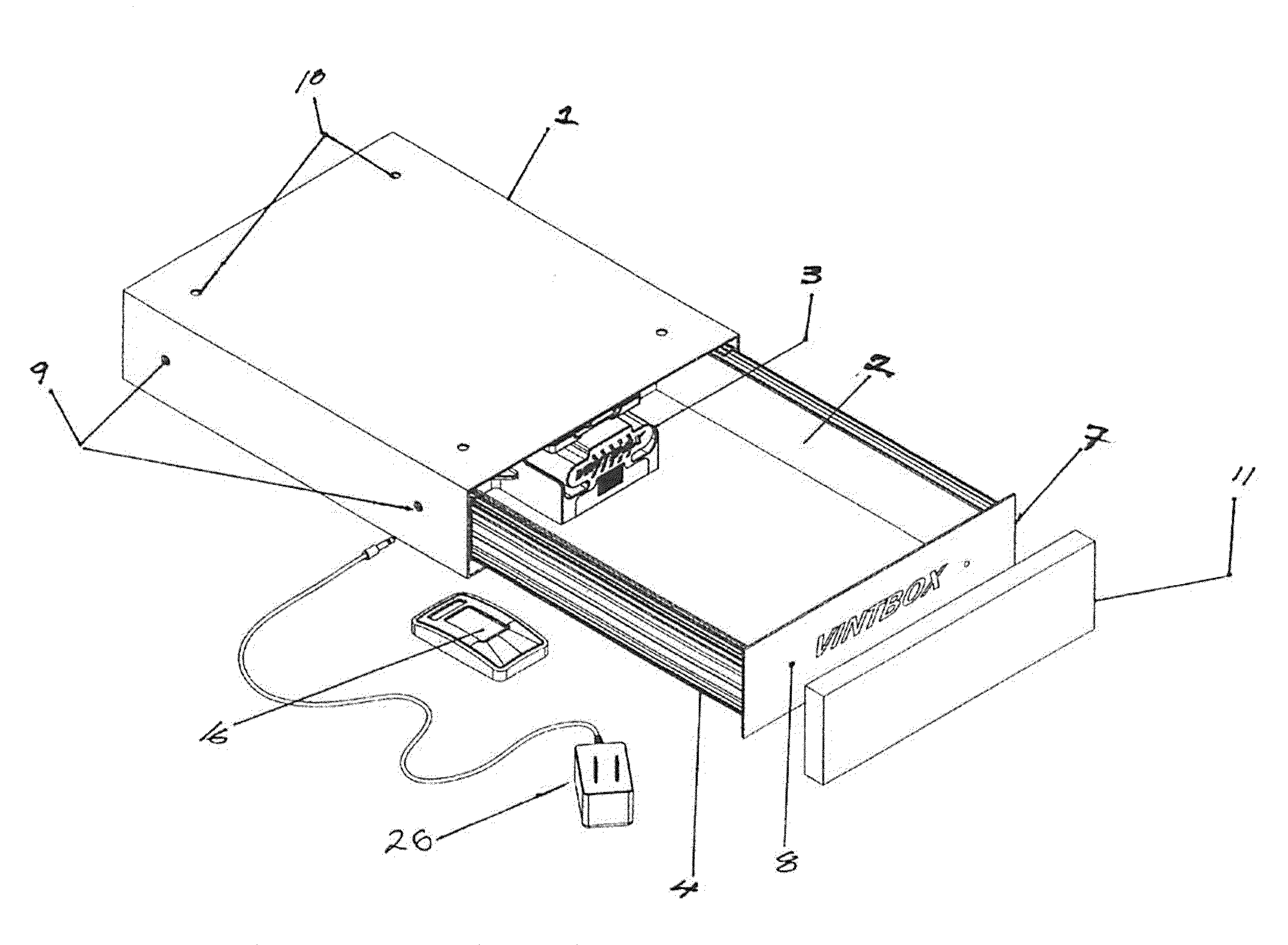
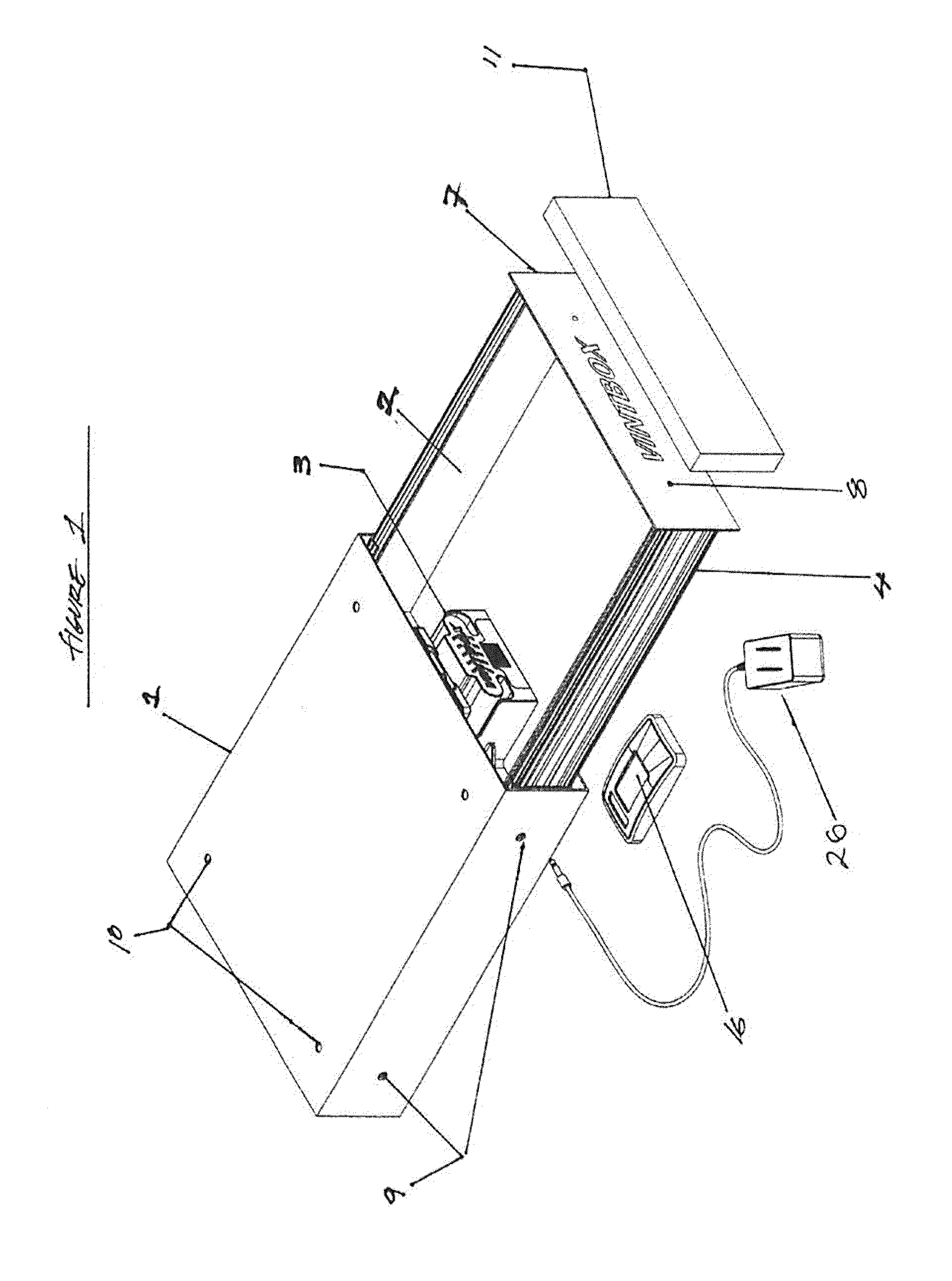
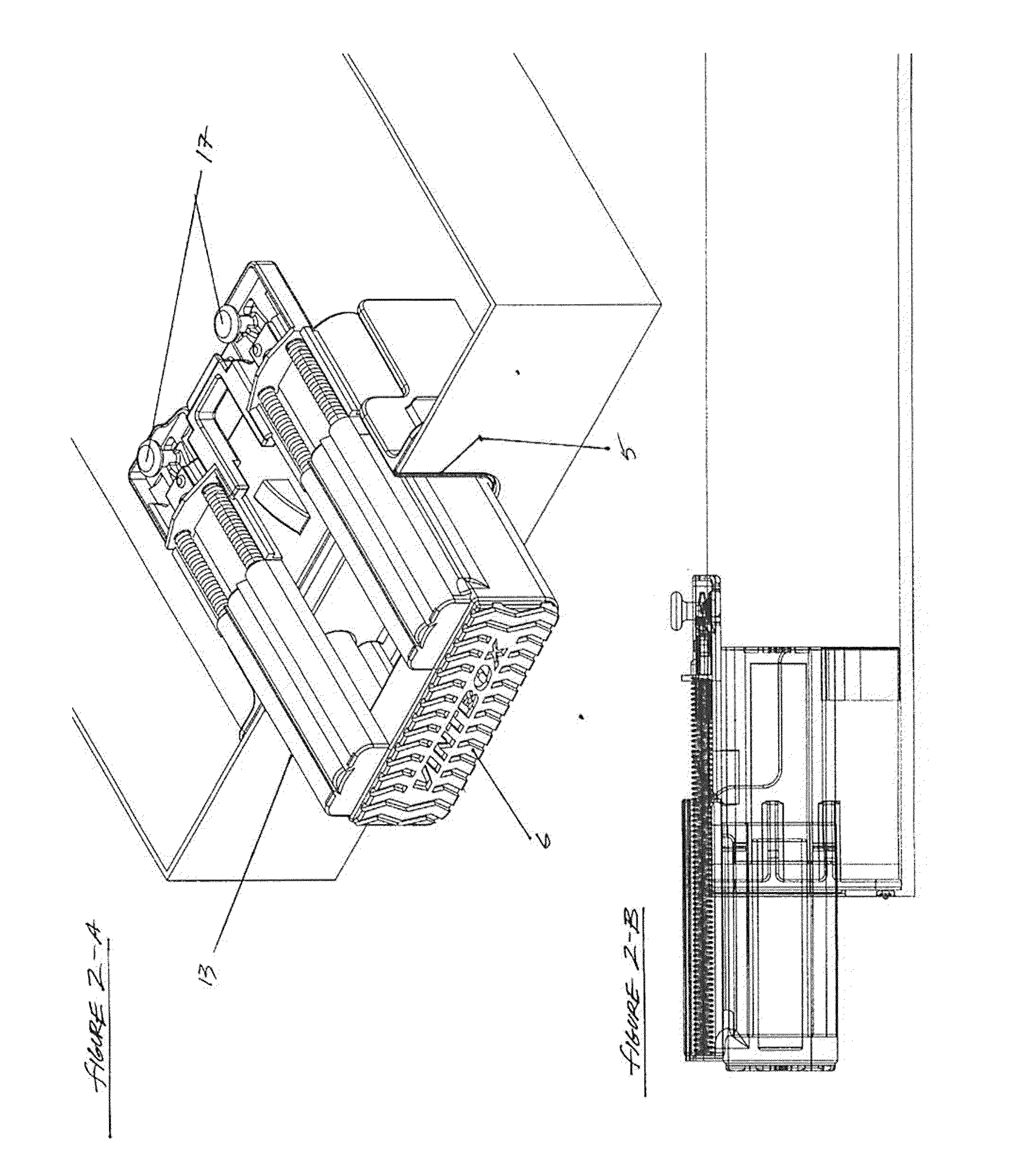
[0018]In the particularly advantageous embodiment of the invention illustrated, as seen in FIG. 1, the device is comprised of a main drawer housing (1), active drawer body (2), drawer glides (4), and central component housing (3) mounted with fasteners to the active drawer body (2), in FIG. 6 showing adaptation to a rear opening (5) in the active drawer body (2) serving as a through way for the linear motion push bar assembly (6), shown fully extended. The housing (1) and drawer (2) are stamped and break pressed fourteen gauge steel sections, including the drawer front (7), and have through holes for side mount option (8) and under mount option (9). Through holes (10) are to permit the mounting on the drawer front (7) of any building material for the purpose of blending in with surroundings where the invention is mounted, e.g., mounting the device in a desk or chest of drawers with a drawer-front matching the woodwork of the surrounding furniture. The central component housing (3) i...
PUM
 Abstract
Description
Claims
Application Information