Screw compressor

Inactive Publication Date: 2010-09-30
HITACHI APPLIANCES INC
View PDF2 Cites 14 Cited by
  • Summary
  • Abstract
  • Description
  • Claims
  • Application Information

AI Technical Summary

Benefits of technology

[0019]According to the invention, since the steel pipe chamber accommodating the motor casing and the main casing is provided, the steel pipe chamber is able to be divided in the axial direction, and the space inside the steel pipe chamber which is ab

Problems solved by technology

For this reason, there is a problem in that the mass of the compressor increases.
At this time, since the oil separator is also made from cast iron, there is a problem in that the mass of the compressor largely increases.
However, the screw compressors of the related art have the following problems.
Due to this, there is a problem in that the motor may be overheated during an operation of the compressor, and the reliability thereof is not satisfactory.
However, in the configuration in which the pressure inside of the steel pipe chamber is dropped to a low pressure, it is difficult to install an oil separator in the steel pipe chamber.
For this reason, it is necessary to install the oil separator separately from the compressor, and hence there is a problem in that the entire compressor increases in size.
In addition, in the case of the structure in which different types of metals, that is, the steel pipe and the cast iron are welded to each other so as to obtain the low pressure portion and the high pressure portion divided from each other, the different types of metals can be welded to each other, but when the optimal welding con

Method used


Image

  • Screw compressor
  • Screw compressor
  • Screw compressor

Examples


first embodiment

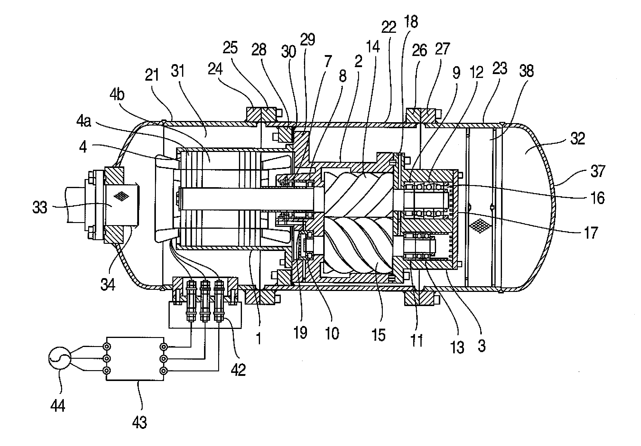
[0029]FIG. 1 shows a first embodiment according to the invention. In the following description, although a twin screw compressor having two male and female screw rotors are exemplified as the embodiment, the invention is not limited to the twin screw compressor, but may be also applied to a single screw compressor having one screw rotor.

[0030]As shown in FIG. 1, a screw compressor includes a motor casing 1, a main casing 2, and a discharge casing 3 which are connected to each other. The motor casing 1 accommodates a driving motor 4 which drives a compression mechanism portion, and is fixed to the main casing 2 through means such as bolts. The main casing 2 is provided with a cylindrical bore 5 and a suction port 6 which introduces a refrigerant gas into the cylindrical bore 5. The cylindrical bore 5 accommodates a female rotor (not shown) and a male rotor 14, rotatably supported by roller bearings 7, 8, and 9 (the low-pressure-side bearings 7 and 8 and the high-pressure-side bearing...

second embodiment

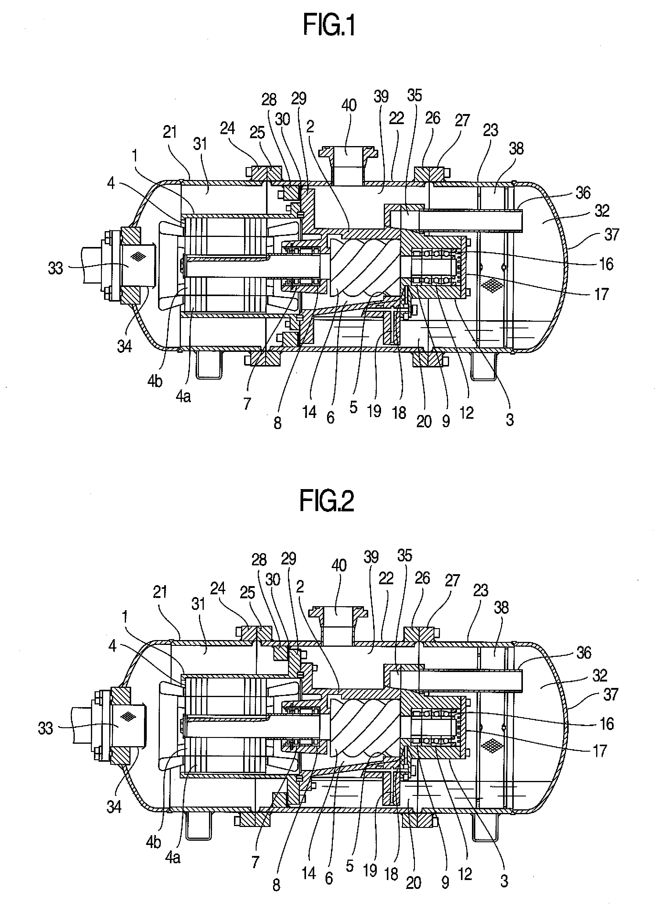
[0045]FIG. 2 shows a second embodiment according to the invention. As in the embodiment of FIG. 1, the steel pipe chamber includes the low-pressure-side chamber 21 and the high-pressure-side chambers 22 and 23. Since the flanges 24, 25, 26, and 27 formed in the chambers are connected to each other through means such as bolts, the low-pressure-side chamber 21 and the high-pressure-side chambers 22 and 23 are sealed from each other, are sealed from the ambient air, and are able to be divided.

[0046]The embodiment is different from the first embodiment in that the flange 29 formed in the motor casing 1 and the flange 28 formed inside the high-pressure-side chamber 22 are connected to each other through bolts with the sealing component 30 interposed therebetween. Even in the embodiment, the spaces 31 and 32 inside the steel pipe chamber are divided into the space 31 as the low-pressure-side space and the space 32 as the high-pressure-side space. Additionally, it is possible to cool the d...

third embodiment

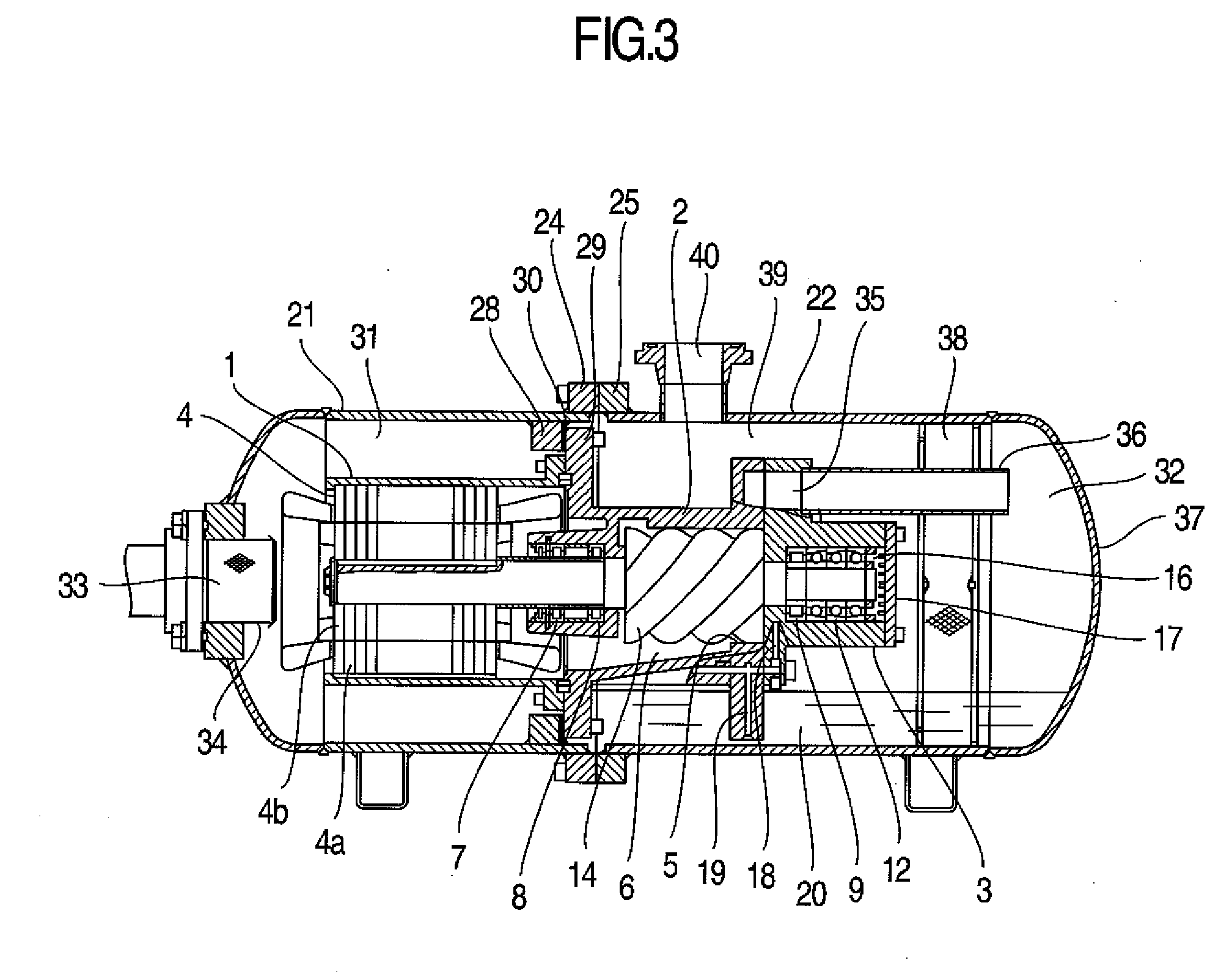
[0047]FIG. 3 shows a third embodiment according to the invention. As in the embodiment of FIG. 1, the steel pipe chamber includes the low-pressure-side chamber 21 and the high-pressure-side chamber 22. In addition, the flanges 24 and 25 formed in the chambers are connected to each other through means such as bolts so as to be sealed from each other, and are able to be divided. In the embodiment, the flange 29 formed in the main casing 2 and the flange 28 formed in the inside of the low-pressure-side chamber 21 are connected to each other through bolts with the sealing component 30 interposed therebetween. The spaces 31 and 32 inside the steel pipe chamber is divided into the space 31 as the low-pressure-side space and the space 32 as the high-pressure-side space. Even in the embodiment, it is possible to cool the driving motor 4 by using the low-pressure and low-temperature refrigerant gas, and to dispose the oil separator in the inside of the steel pipe chamber. Further, it is poss...


PUM


Abstract

In order to obtain a screw compressor which is small in size and weight and has ease of maintenance and high reliability, the screw compressor comprises a screw rotor, a low-pressure-side bearing and a high-pressure-side bearing which support the screw rotor, a motor which drives the screw rotor, a motor casing which accommodates the motor, a main casing which accommodates the screw rotor and the low-pressure-side bearing, and a discharge casing which accommodates the high-pressure-side bearing. The motor casing, the main casing, and the discharge casing are accommodated in a steel pipe chamber, and the steel pipe chamber includes a low-pressure-side chamber and a high-pressure-side chamber which are able to be divided in the axial direction. By using a flange provided on an inner surface of the steel pipe chamber, a flange provided in the main casing, and a sealing component provided between the flanges, the steel pipe chamber is divided into a low-pressure-side space and a high-pressure-side space.

Description

FIELD OF THE INVENTION[0001]The present invention relates to a screw compressor which compresses a fluid, and particularly, to a screw compressor which is used in a refrigeration cycle of an air conditioner, a refrigerating machine, or the like.DESCRIPTION OF RELATED ART[0002]In a screw compressor, a screw rotor having a three-dimensionally twisted curved surface is provided as a compression mechanism portion. For this reason, generally, a casing accommodating the compression mechanism portion is made from cast iron which is able to be formed in a complex shape. The cast iron generally used for the casing of the compressor has strength lower than that of steel for pressure pipe. In the case where a design pressure is the same, the cast iron casing needs to be thicker than the steel casing. For this reason, there is a problem in that the mass of the compressor increases. In addition, in the screw compressor, lubricant contained in a discharge gas needs to be separated. For this reaso...

Claims


Application Information

Patent Timeline
IPC IPC(8): F04C18/16
CPCF01C21/10F04C23/008F04C18/16
Inventor KATO, EISUKEURASHIN, MASAYUKIYONEMOTO, RYUICHIROYAMADA, SHINICHIROTOJO, KENJI
Owner HITACHI APPLIANCES INC
Why Eureka
Try Eureka