Snap together split sprocket

a split sprocket and sprocket technology, applied in the field of split sprockets, can solve the problems of substantial increase in costs, substantial decrease in productivity, and cumbersome disassembly or disassembly of this type of split sprocket, and achieve the effects of reducing the time required to install and remove the sprocket from the shaft, reducing costs, and less downtim

Inactive Publication Date: 2010-10-28
EPIC POLYMER SYST CORP
View PDF15 Cites 14 Cited by
  • Summary
  • Abstract
  • Description
  • Claims
  • Application Information

AI Technical Summary

Benefits of technology

[0013]One benefit of the invention is that the time required to install and remove the sprocket from the shaft is significantly reduced relative to conventional split sprockets that rely on either fasteners or welding for assembly. This results in less downtime for any machinery that relies on the sprockets of the present invention relative to conventional split sprockets, and also means that fewer man-hours are required to install and remove the sprockets of the present invention, further decreasing costs.
[0014]Another benefit of the invention is that in addition to saving a sprocket user time and money during sprocket installation and removal, the sprocket of the present invention is also easier and cheaper and faster to manufacture that conventional split sprockets. For example, a manufacturer does not need to pay for expensive metal fasteners or drill holes to prepare the sprocket to receive fasteners. The sprocket of the present invention can consequently typically be manufactured for 20%-30% less than conventional split sprockets.

Problems solved by technology

Consequently, assembling or disassembling this type of split sprocket can be quite cumbersome.
It can take roughly fifteen minutes for a person to assemble or disassemble this type of split sprocket, and if several of these sprockets need to be assembled or disassembled at any one time, the amount of time required can result in substantial decreases in productivity and substantial increases in costs.
However, welding is a time consuming process and requires hiring a relatively expensive welder.
Consequently, just as when fasteners are used in split sprocket assembly, welding can also result in substantial decreases in productivity and substantial increases in costs.

Method used


Image

  • Snap together split sprocket
  • Snap together split sprocket
  • Snap together split sprocket

Examples


Embodiment Construction

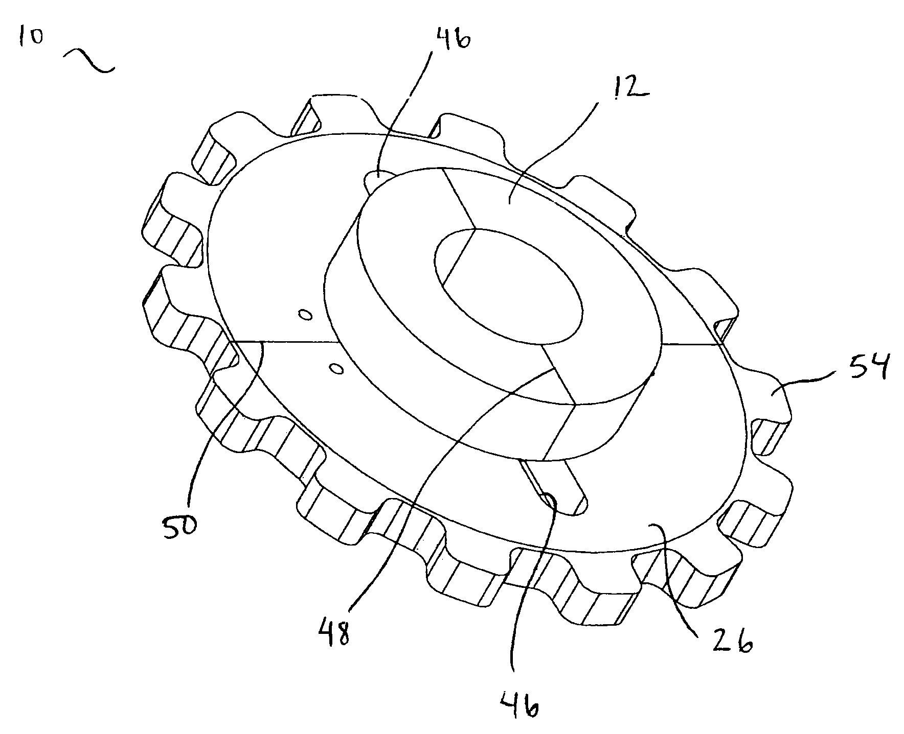
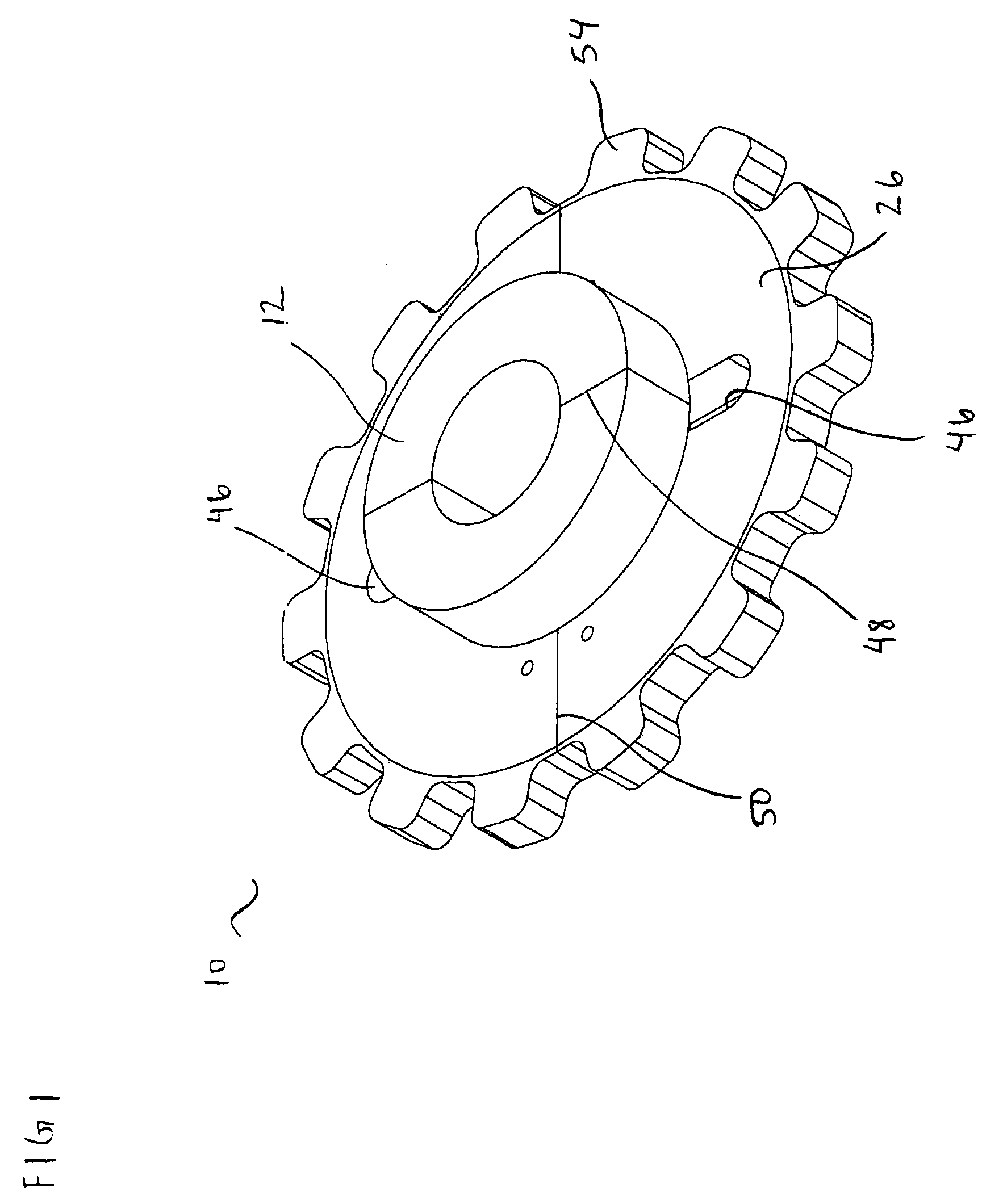
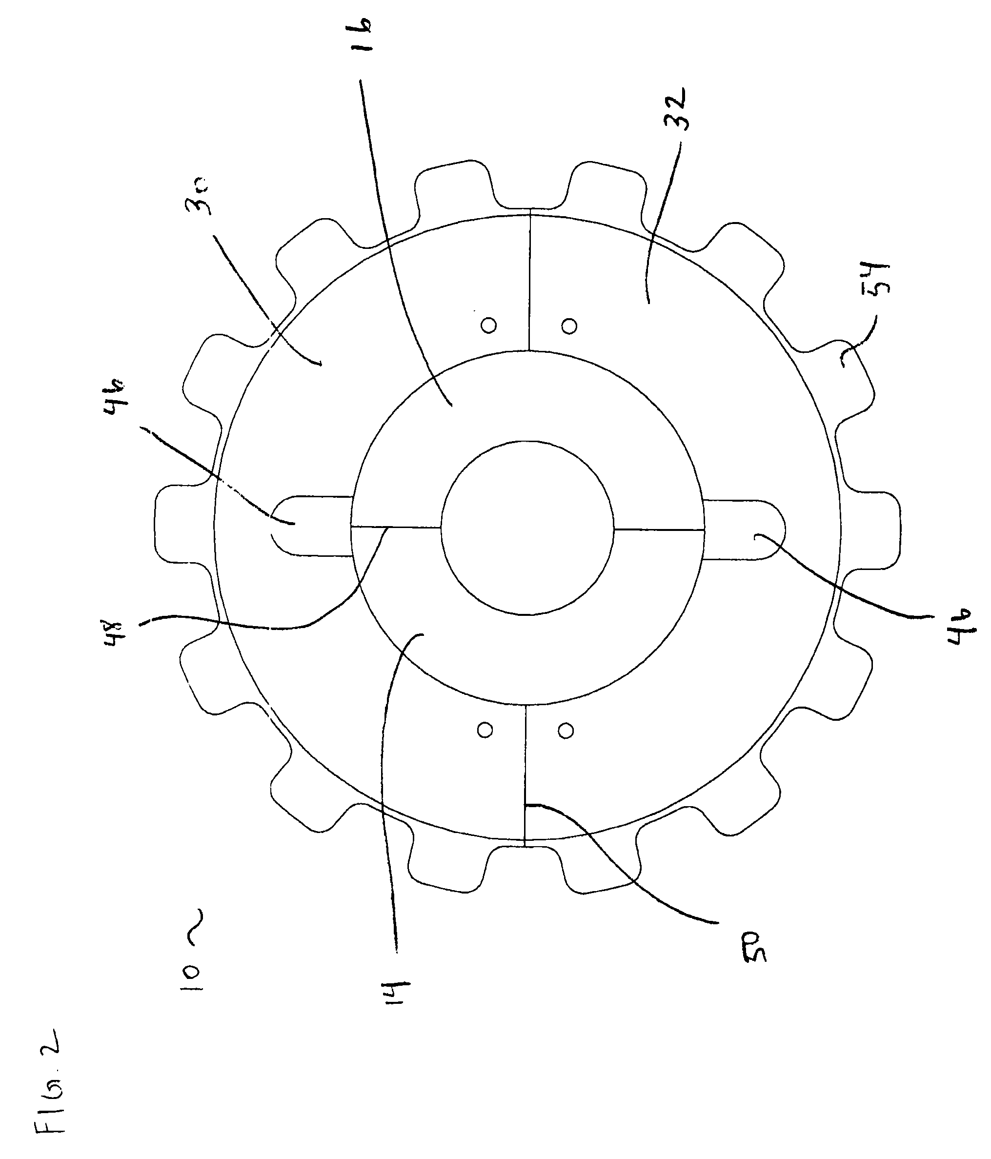
[0023]Sprockets are manufactured in various shapes and sizes and for a variety of purposes. Sprockets include drive sprockets, which are disposed on a driven shaft for transferring energy to a perforated material such as a chain or track; idler sprockets, which do not impart additional energy to the perforated material but are used for purposes such as maintaining tension in the perforated material; and toothless sprockets, which are sprockets that do not use teeth to interface with the perforated material. The conventional “split sprocket” is a type of sprocket that typically includes four components, a two-part hub and a two-part plate that interfaces with the perforated material (“material-interfacing plate”), all of which is held together with nuts and bolts. Advantageously, the split sprocket can be clamped to a shaft at any point along the shaft; disadvantageously, the conventional split sprocket is typically held together using fasteners or welding. Consequently, assembly and...


PUM


Abstract

Described herein is a sprocket for interfacing with a perforated material, such as a chain. The sprocket includes a hub and a material-interfacing plate. The hub is shaped to fit around an axially extending shaft, and includes a plurality of hub portions each shaped to fit around a portion of the shaft; and a retaining portion and a hub interlocking portion, each disposed on at least one of the hub portions. The material-interfacing plate has a periphery that is shaped to interface with the perforated material, and includes a plurality of plate portions each shaped to fit around a portion of the hub; and a plate interlocking portion shaped to interlock with the hub interlocking portion and disposed on at least one of the plate portions. The material-interfacing plate is in a secured position when the plate interlocking portion and the hub interlocking portion are interlocked with each other. The interlocked plate and hub interlocking portions prevent the material-interfacing plate from sliding radially off the hub and the retaining portion prevents the material-interfacing plate from sliding axially off the hub when the material-interfacing plate is in the secured position.

Description

FIELD OF THE INVENTION[0001]The present invention relates to a split sprocket that can be assembled without relying on fasteners or welding to hold the various components of the sprocket together.BACKGROUND OF THE INVENTION[0002]Sprockets are products that are shaped to rotate on a shaft and to interface with an indented or a perforated material such as a chain or track. A common type of sprocket known in the art is a “split sprocket”, which is a type of sprocket that typically includes four components, a two-part hub and a two-part material-interfacing plate, all of which are held together with nuts and bolts. The fact that the sprocket is split allows it to be clamped on to the shaft at any point along the shaft, as opposed to having to receive the shaft at one end thereof and then slid along the shaft to a desired position. Typically, eight nuts and bolts are used to hold together this type of split sprocket. Consequently, assembling or disassembling this type of split sprocket c...

Claims


Application Information

Patent Timeline
Patent Type & Authority Applications(United States)
IPC IPC(8): F16H55/30
CPCF16H55/12F16H55/46F16H55/30
Inventor CURLEY, PATRICK L.FULTON, WILLIAM R.
Owner EPIC POLYMER SYST CORP
Why Eureka
Try Eureka