Image processing apparatus and image processing method

a technology which is applied in the field of image processing apparatus and image processing method, can solve the problems of high calculation cost, continuous shooting speed drop, and inability to buffer image data, and achieve the effect of effective correction

Inactive Publication Date: 2010-11-25
CANON KK
View PDF14 Cites 20 Cited by
  • Summary
  • Abstract
  • Description
  • Claims
  • Application Information

AI Technical Summary

Benefits of technology

[0012]According to these aspects, a blur of image capturing data that occurs due to vibration can be effectively corrected.

Problems solved by technology

The hardware image-stabilization method poses problems about an increase in number of components and that in manufacturing cost.
However, the methods of Japanese Patent Laid-Open Nos. 2006-74693 and 2006-86762 suffer the following problems.
However, a process for accurately calculating a vibration amount and that for deforming and synthesizing images in correspondence with the vibration amount require very high calculation cost, resulting in a continuous shooting speed drop and a decrease in number of image capturing data that can be buffered.

Method used


Image

  • Image processing apparatus and image processing method
  • Image processing apparatus and image processing method
  • Image processing apparatus and image processing method

Examples


first embodiment

[0033][Arrangement of Camera]

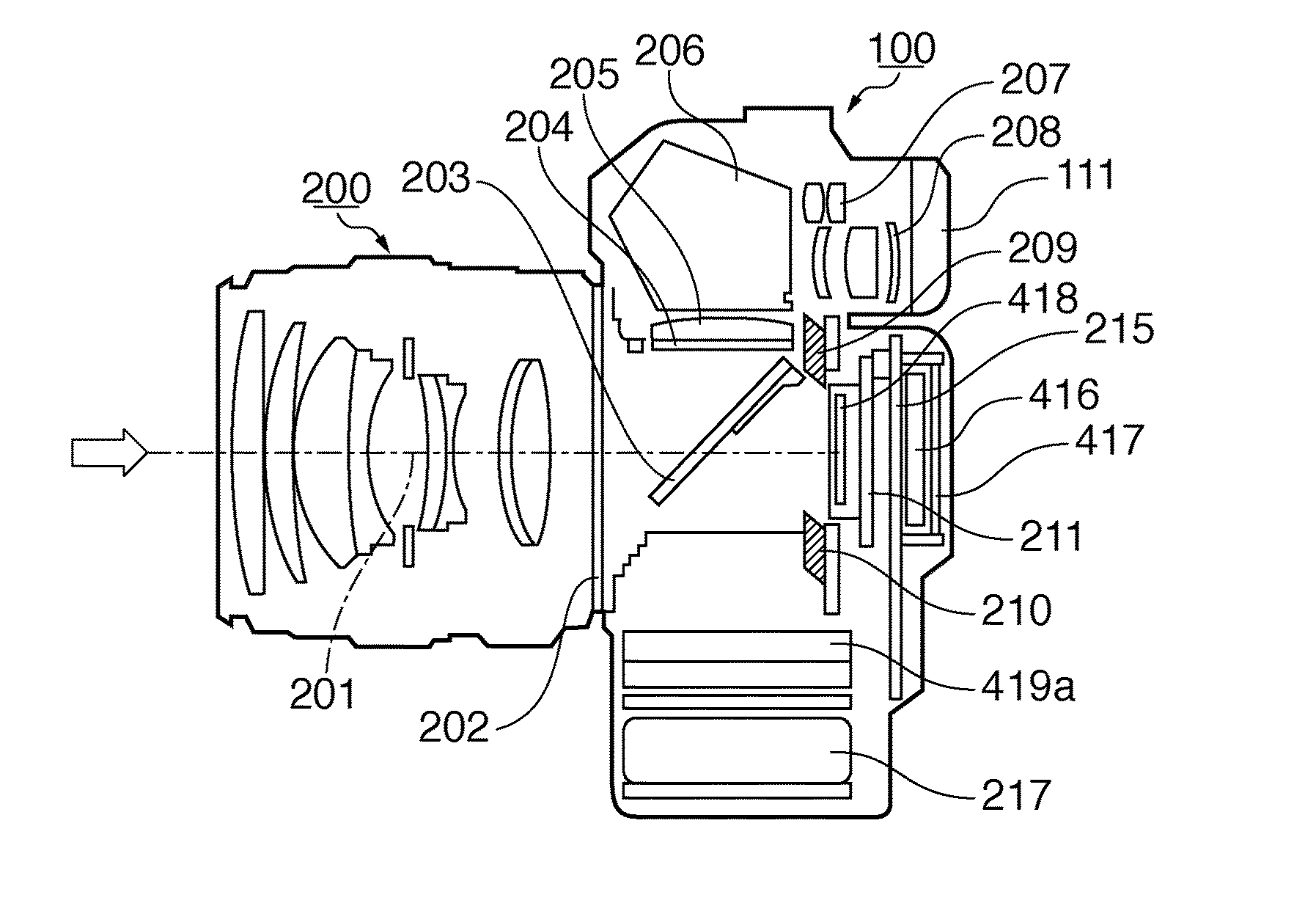
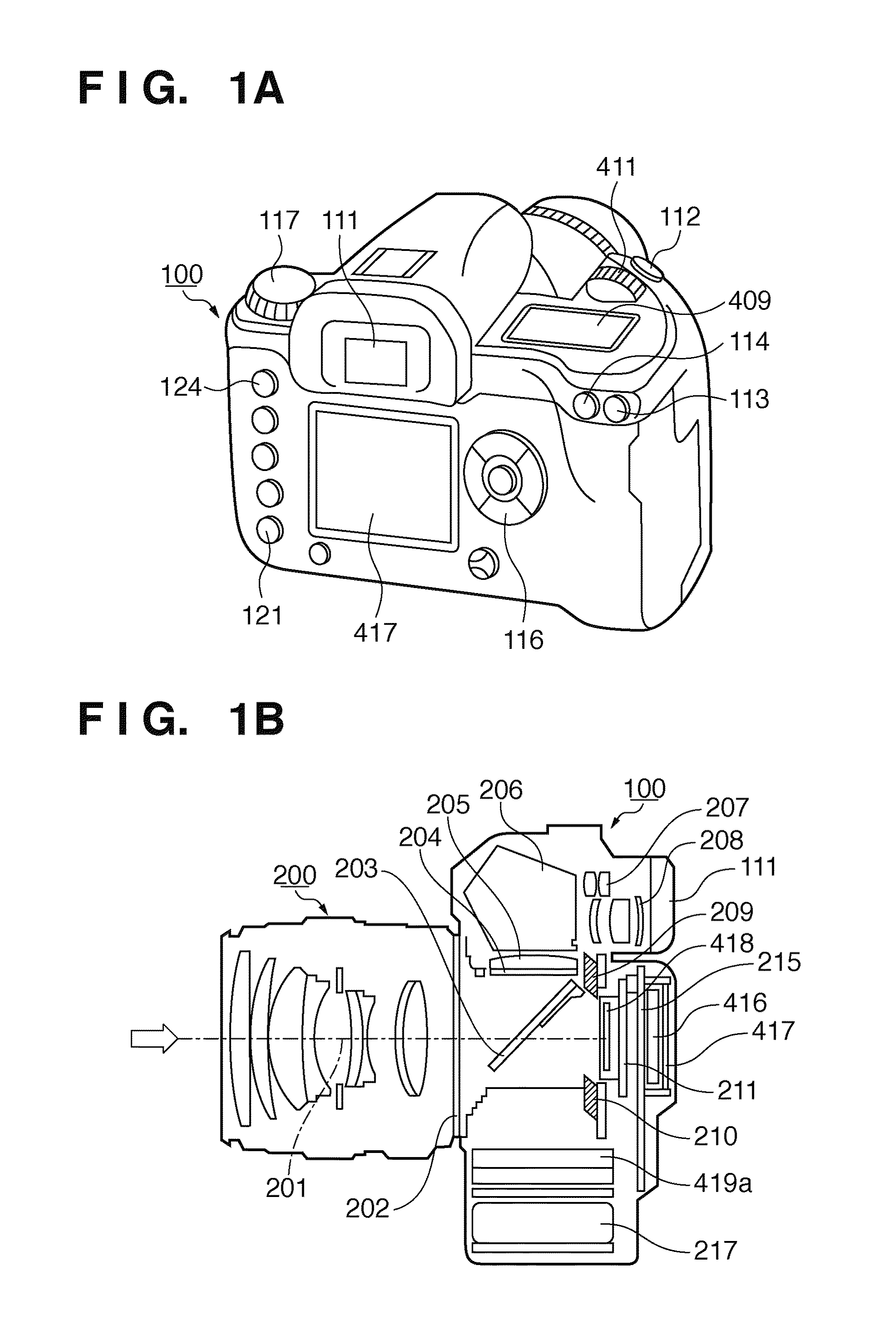
[0034]FIGS. 1A and 1B are respectively an external view and cross-sectional view of a digital camera.

[0035]A viewfinder eyepiece 111, auto-exposure (AE) lock button 114, button 113 used to select auto-focus (AF) points, and release button 112 used to start an imaging operation are arranged on the top portion of a camera body 100. Also, an imaging mode selection dial 117, external display unit 409, digital dial 411, and the like are arranged.

[0036]The digital dial 411 serves as a multi-function signal input unit which is used to input a numerical value to the camera in cooperation with another operation button and to switch an imaging mode. The external display unit 409 as an LCD panel displays imaging conditions including a shutter speed, stop, and imaging mode, and other kinds of information.

[0037]On the back surface of the camera body 100, a liquid crystal display (LCD) monitor 417 which displays an image caught by the camera, that captured by the came...

second embodiment

[0124]Image processes according to the second embodiment of the present invention will be described below. Note that the same reference numerals in the second embodiment denote the same components as those in the first embodiment, and a detailed description thereof will not be repeated.

[0125]The first embodiment has explained the method of implementing the process equivalent to coded exposure using time-divisionally exposed images and a divide pattern. Also, the first embodiment has explained the example of the divide pattern generation method. The second embodiment will explain another divide pattern generation method.

[0126]FIGS. 14A to 14C are views for explaining images used to generate motion information.

[0127]In order to obtain motion information, at least an image captured when a shutter transits from a close state to an open state and that captured when the shutter transits from the open state to the close state are required. That is, when motion information is generated from...

third embodiment

[0131]Image processes according to the third embodiment of the present invention will be described below. Note that the same reference numerals in the third embodiment denote the same components as those in the first and second embodiments, and a detailed description thereof will not be repeated.

[0132]The above embodiments have explained the method of generating a random pattern as a divide pattern. When synthesis images and motion detection images are randomly divided, the motion detection images are divided irrespective of displacement amounts of images. As a result, an actual exposure amount is reduced, and an adjustment coefficient of a gain adjustment process required to compensate for the reduced exposure amount is increased, thus posing a problem of an increase in noise.

[0133]When a plurality of short exposure images are acquired by time-division exposure, and are divided to implement an image stabilization process, images within a predetermined exposure time can always be ac...


PUM


Abstract

A plurality of image capturing data time-divisionally exposed by a capturing unit are input, and are divided into synthesis images or motion detection images. A motion amount of the capturing unit at the time of time-division exposure is detected from the image capturing data of the motion detection images, and synthesized image capturing data is generated by synthesizing the synthesis images. Then, a vibration of the synthesized image capturing data is corrected based on a divide pattern indicating divisions, and the motion amount.

Description

BACKGROUND OF THE INVENTION [0001]1. Field of the Invention[0002]The present invention relates to an image processing apparatus and image processing method, which corrects a blur of image capturing data that occurs due to vibration.[0003]2. Description of the Related Art[0004]A digital image easily allows an enlarged-scale displays to be displayed over 100% when using a personal computer. In an enlarged image, an image blur caused by even the slightest camera shake will stand out. For this reason, as image capturing devices for digital cameras gain higher resolutions, a process for correcting a camera shake that occurs at the time of imaging has received a lot of attention.[0005]An image-stabilization method includes those implemented by hardware and software. In the hardware method, a gyro sensor is mounted on a camera, and the effects of a camera shake are eliminated by driving a lens and image capturing device to cancel vibrations of the camera during exposure based on an output ...

Claims


Application Information

Patent Timeline
Patent Type & Authority Applications(United States)
IPC IPC(8): H04N5/228
CPCG06T5/003H04N5/23248G06T2207/20201H04N23/68H04N5/265H04N23/951
Inventor KOTANI, TAKUYA
Owner CANON KK
Why Eureka
Try Eureka