Thin-film layered centrifuge device and analysis method using the same

a centrifuge and thin film technology, applied in centrifuges, laboratory glassware, instruments, etc., can solve problems such as leakage during centrifugation, inability to complete closing, and deterioration of assay reliability and accuracy

Active Publication Date: 2010-11-25
NEXUS DX
View PDF8 Cites 71 Cited by
  • Summary
  • Abstract
  • Description
  • Claims
  • Application Information

AI Technical Summary

Benefits of technology

[0009]Therefore, it is one aspect of the present invention to provide a thin film layered centrifuge device wherein a thin-film rotatable body is integrated with an apparatus to diagnose and detect a small amount of materials present in fluids, such as a lab-on-a-chip, a protein chip and a DNA chip, and an analysis method using the same. Embodiments provide a thin film centrifuge device in which bio chips, such as a lab-on-a-chip, protein chips and DNA chips, to diagnose and detect a material in a fluid are integrated, by providing a thin film body with a centrifuge device causing no leakage, when specimens are extracted from samples by centrifugation, and an analysis method using the same.

Problems solved by technology

However, these valves inevitably allow opening based on physical movement, thus entailing incomplete closing.
Accordingly, inherent hydraulic pressure of fluids may cause leakage during centrifugation.
This leakage prevents extraction of desired amounts of specimens from samples by centrifugation, thus causing deterioration in assay reliability and accuracy.
That is, when the body ceases rotation, through the U- or V-shaped hydrophilic channel, only a part of the specimen in the specimen chamber may be transferred to the assay site, thus making quantitative analysis impossible.
In this case, erythrocyte is admixed with blood serum again, making extraction of only blood serum difficult.
That is, when the body stops, strong capillary action of the bottle neck channel composed of the thin film channel and absence of outlet in the remnant chamber make it impossible to freely transfer the fluids from the remnant chamber to the specimen chamber.

Method used


Image

  • Thin-film layered centrifuge device and analysis method using the same
  • Thin-film layered centrifuge device and analysis method using the same
  • Thin-film layered centrifuge device and analysis method using the same

Examples


Embodiment Construction

[0087]Reference will now be made in detail to the embodiments of the present invention, examples of which are illustrated in the accompanying drawings, wherein like reference numerals refer to like elements throughout.

[0088]Reference will now be made in detail to the embodiments of the present invention, examples of which are illustrated in the accompanying drawings, wherein like reference numerals refer to like elements throughout.

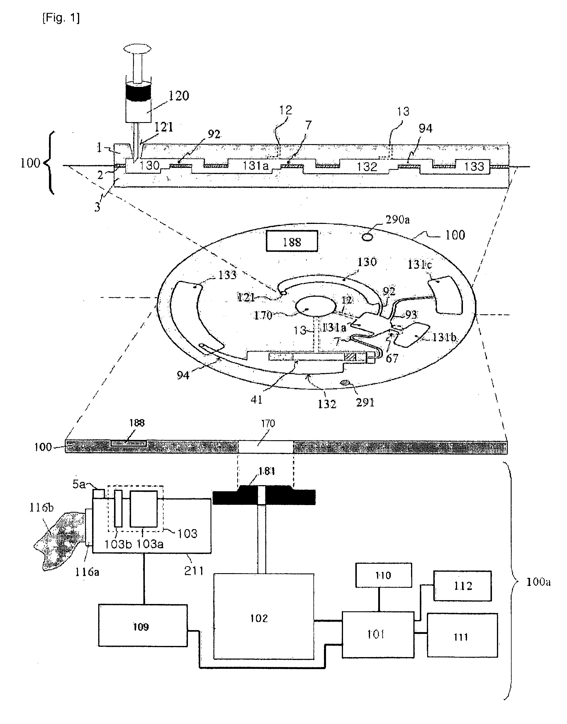
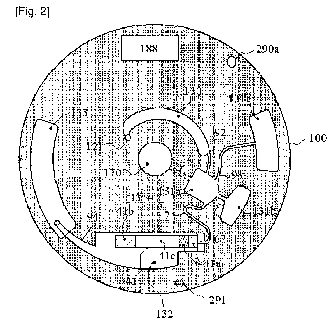
[0089]FIGS. 1 and 2 are a sectional view and a plan view illustrating a thin film layered centrifuge device and a thin film layered centrifuge device drive to control operation of the device according to one embodiment of the present invention.

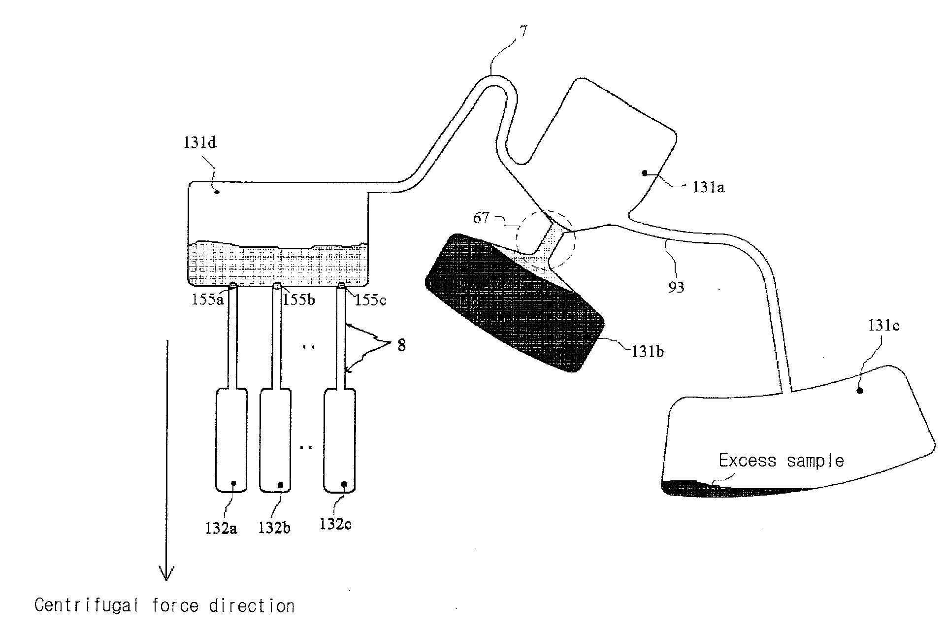
[0090]Referring to FIGS. 1 and 2, the thin film centrifuge device may be realized by integrating a lab-on-a-chip in thin film devices such as conventional disc devices including CD-ROMs and DVDs. For example, in one embodiment, provided are a thin film centrifuge device 100 in which one or more chambers 130, 131a, 1...


PUM

PropertyMeasurementUnit
thicknessaaaaaaaaaa
heightaaaaaaaaaa
thicknessaaaaaaaaaa

Abstract

Disclosed herein is a thin-film layered centrifuge device and an analysis method using the same. One example of an embodiment of the present invention is a thin film layered centrifuge device where a device, such as a lab on a chip, a protein chip and a DNA chip, for diagnosing and detecting a small amount of material in a fluid is integrated into a rotatable thin-film layered body, and to an analysis method using the thin-film layered centrifuge device.

Description

BACKGROUND[0001]1. Field[0002]Embodiments of the present invention relate to a thin film layered centrifuge device and an analysis method using the same. More specifically, embodiments of the present invention relate to a thin film layered centrifuge device wherein a thin-film rotatable body is integrated with an apparatus to diagnose and detect a small amount of materials present in fluids, such as a lab-on-a-chip, a protein chip and a DNA chip, and an analysis method using the same.[0003]2. Description of the Related Art[0004]General clinical diagnosis and analysis apparatuses to detect a small amount of analytes in fluids include multiple sample arrangement and automated sample feed devices, and have a structure in which an apparatus to analyze a large number of test samples in series or parallel is integrated on a rotatable thin film body to improve analysis efficiency and economic efficiency. For example, rotatable bio discs are one type of such analyzers. Such thin-film analyz...

Claims


Application Information

Patent Timeline
Patent Type & Authority Applications(United States)
IPC IPC(8): C12Q1/68B04B7/08C12M1/34
CPCG01N35/00029G01N35/00069G01N33/5302G01N2035/00495B01L3/502753G01N2035/00247B04B1/02C12M1/10C12Q1/68C12Q2565/625
Inventor YOO, JAE CHERN
Owner NEXUS DX
Why Eureka
Try Eureka