Device for feeding liquid to inkjet heads and device for wiping inkjet heads

a technology for inkjet heads and liquid feeding devices, applied in printing and other directions, can solve the problems of increasing the size of the liquid feeding device, increasing the cost of the device, and complicated structure of the device, and achieves the effects of preventing the ejection of liquid materials, ensuring excellent responsiveness, and simplifying the structure of all pipe lines

Active Publication Date: 2010-12-09
ISHII HYOKI
View PDF5 Cites 0 Cited by
  • Summary
  • Abstract
  • Description
  • Claims
  • Application Information

AI Technical Summary

Benefits of technology

[0081]As described above, in the liquid feeding device for inkjet heads according to the present invention which is accomplished to attain the first technical object, even when the liquid material fed from one ink tank flows into the common liquid feed pipe line together with the gas, the gas is released into the atmosphere from the separate gas flow pipe lines through the common gas flow pipe line which is opened to the atmosphere. As a result, it is possible to avoid the situation in which the gas flows through the separate liquid feed pipe lines together with the liquid material and remains in each of the inkjet heads, and to effectively prevent the ejection of the liquid material from each of the inkjet heads from inhibiting. Further, while the liquid material flows from the common liquid feed pipe line to each of the separate liquid feed pipe lines and remains in each of the inkjet heads, the gas is rapidly released from the common gas flow pipe line through the separate gas flow pipe lines, so the liquid materials flowing to each of the inkjet heads mutually have the uniform pressure. As a result, there occurs no variation in ejection of the liquid material from each of the inkjet heads and it becomes possible to eject the liquid material from each of the inkjet heads in a state where excellent responsiveness is secured. Further, the separate liquid feed pipe lines are each connected to the common gas flow pipe line which can be opened to the atmosphere, thereby simplifying the structures of all the pipe lines for circulating the liquid material and the gas. In addition, it is possible to reduce the number of the control means constituted by valve means and the like, for controlling starting and stopping of feeding of the liquid material from the ink tank to each of the inkjet heads, and also reduce the number of control means constituted by valve means and the like for releasing and enclosing the gas with respect to the atmosphere, thereby making it possible to simplify the structure of the liquid feeding device and reduce the manufacturing costs.
[0082]Further, in the liquid feeding device for inkjet heads according to the present invention which is accomplished to attain the second technical object, only a part of the deaerating tube, which has gas permeability and is made of a synthetic resin, is covered with the deaerating unit in the liquid feeding direction, and the internal flow path of the deaerating tube is a single path. For this reason, when the liquid material is flown into the deaerating unit, a stirring flow, turbulence, or the like due to stagnation of the flow of the liquid material is not generated. As a result, there occurs no situation in which air bubbles are generated in the liquid material provided in the deaerating tube and the amount of the dissolved gas is increased. In addition, the inhibition of the ejection of the liquid material due to the air bubbles can be suppressed as much as possible. Further, there is no need to set the inner diameter of the deaerating tube to be as small as that of each unit hollow fiber of the conventional hollow fiber membrane, so it is possible to reduce the flow resistance and smoothly feed the liquid material even at low pressure. This contributes to the reduction in manufacturing costs, prevention of breakage of the liquid feed path, and the reduction in pressure drop, and makes it possible to perform deaeration while smoothly feeding the liquid material even when the liquid material having high viscosity is used. In addition, in the case of cleaning the liquid feed path, it is sufficient to clean the internal flow path of the deaerating tube which is smoothly and continuously formed. Accordingly, as compared with the conventional case of using the hollow fiber membrane, the cleaning of the deaerating unit can be performed with ease and reliability, and there hardly arise a problem in that the liquid material, foreign matters, or solidified materials thereof are attached to the internal flow path and the like, which inhibits the feeding of the liquid material. In addition, when the deaerating unit is mounted to the liquid feed path, it is sufficient to cover a desired part of the deaerating tube by the enclosure. As a result, it is possible to avoid the problem in that the position for disposing the deaerating unit is unambiguously determined, and the degree of freedom of layout in the case of disposing the deaerating unit is increased. Further, application of the inkjet head liquid feed device to a large printer including a plurality of inkjet heads contributes to compactization, and makes it possible to easily perform the maintenance work.
[0083]Further, in the inkjet head wiping device according to the present invention which is accomplished to attain the third technical object, the cleaning mobile unit having the vacuum nozzle is structured such that all the components thereof are completely separated from the inkjet head so as to be maintained in a contactless state. Accordingly, the following problems do not arise. That is, the generation of flaws due to the contact between some of the components of the cleaning mobile unit and the inkjet head, the deterioration in durability due to the generation of flaws, the attachment of foreign matters such as wear dust to the liquid material ejection port of the inkjet head and the vicinity thereof, the ejection failure of the liquid, the printing failure or an oriented film formation failure, and the negative pressure suction failure, due to the attachment of the foreign matters, and the like. In addition, there occurs no situation in which the cleaning mobile unit and the inkjet head are brought into contact with each other through the intermediation of the liquid columns of the cleaning fluid. As a result, there is no need to strictly determine the positional relationship therebetween, the structure required for the positioning is simplified, and the assembly operation can be easily performed, thereby reducing the manufacturing costs.
[0084]Further, in the inkjet head wiping device according to the present invention which is accomplished to attain the fourth technical object, there are provided the cleaning mobile unit having the vacuum nozzle and the gas injection nozzle. Accordingly, as compared with the case of sucking the foreign matters or the like from the cleaning portion only by the suction force of the vacuum nozzle, the cleaning portion can be more reliably cleaned, and the whole amount or the substantially whole amount of the gas to be sucked by the vacuum nozzle can be obtained as the gas injected from the gas injection nozzle. As a result, it is possible to avoid the problem in that the contaminated air, the dust, or the like provided in the vicinity thereof are sucked by the vacuum nozzle. In addition, it is possible to effectively avoid the problem which arises when the cleaning fluid is used as in the conventional case, that is, the problem in which the cleaning fluid enters the inkjet head through the liquid material ejection ports of the inkjet head to be mixed into the liquid material, thereby lowering the concentration of the liquid material.

Problems solved by technology

As a result, the liquid feeding device is increased in size, a structure thereof is complicated, and costs thereof are increased.
Also with this structure, the necessary number of the liquid feed pipe lines 61, each of which directly communicates with the ink tank 60 and with each of the inkjet heads 62, corresponds to the number of the inkjet heads 62 to be provided, with the result that the size of the liquid feeding device is increased and the costs thereof are increased.
In addition, the liquid material is fed with a uniform pressure with respect to each of the inkjet heads 62, so it is necessary to set lengths of the plurality of liquid feed pipe lines 61 to be equal to each other, which also increases the size of the liquid feeding device and raises the costs.
This causes an ejection failure of the liquid material, and inhibits the printing on the print medium and formation of the oriented film.

Method used


Image

  • Device for feeding liquid to inkjet heads and device for wiping inkjet heads
  • Device for feeding liquid to inkjet heads and device for wiping inkjet heads
  • Device for feeding liquid to inkjet heads and device for wiping inkjet heads

Examples


first embodiment

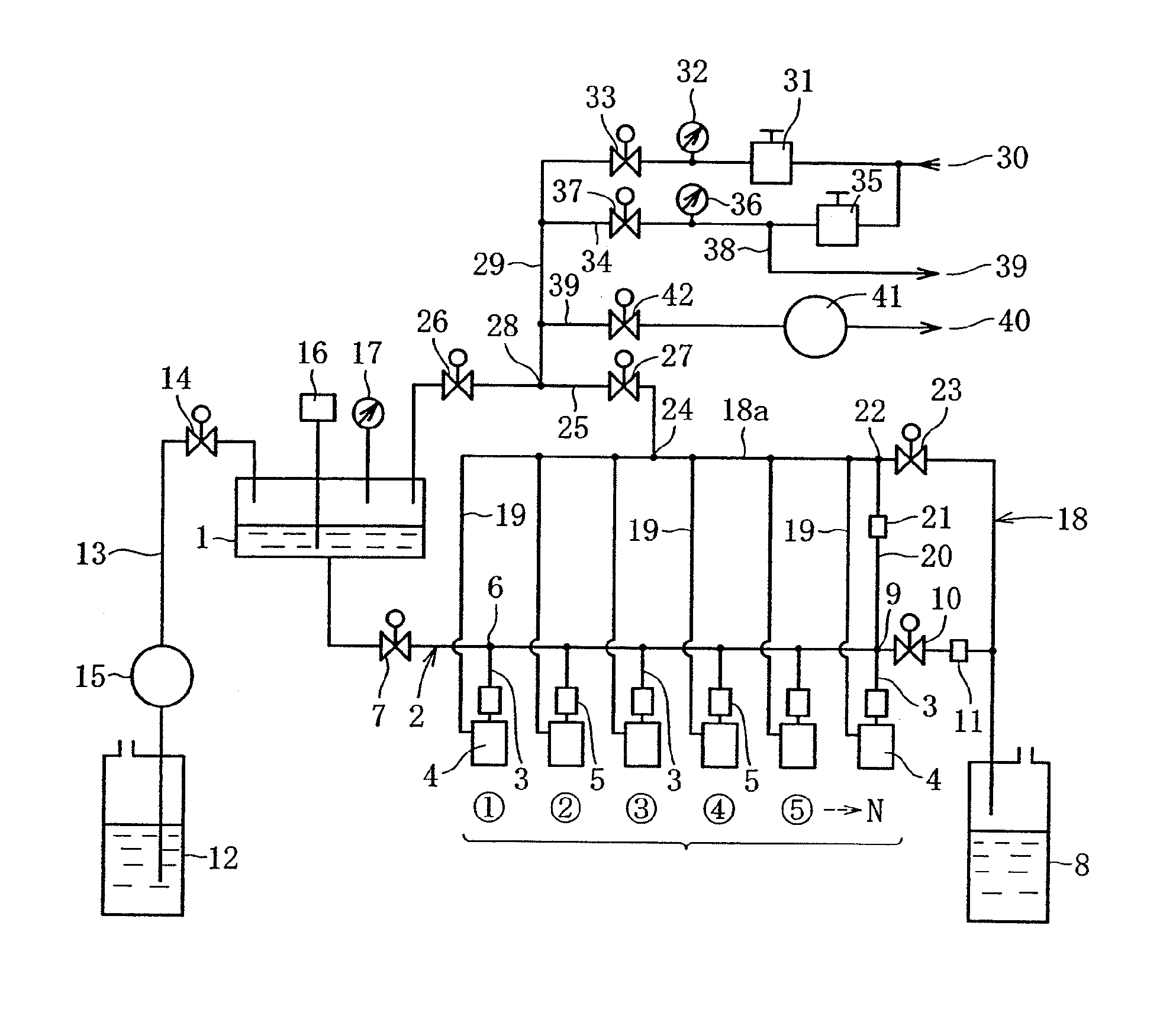
[0109]FIG. 1 illustrates a liquid feeding device for inkjet heads according to a first embodiment of the present invention. As illustrated in the figure, in the liquid feeding device for inkjet heads according to the first embodiment, an ink tank 1 for storing a liquid material communicates with a common liquid feed pipe line 2 extending in a horizontal direction at a position below the ink tank 1, and a plurality of separate liquid feed pipe lines 3 are each connected to the common liquid feed pipe line 2 at the same intervals. The separate liquid feed pipe lines 3 each extend downward from the common liquid feed pipe line 2, a lower end of each of the separate liquid feed pipe lines 3 is connected to each of inkjet heads 4 (liquid pool provided inside thereof), and deaerating means 5 for removing bubbles of air or the like contained in the liquid material is provided halfway in a longitudinal direction thereof. Note that 6 inkjet heads 4 are provided in the illustrated example, bu...

second embodiment

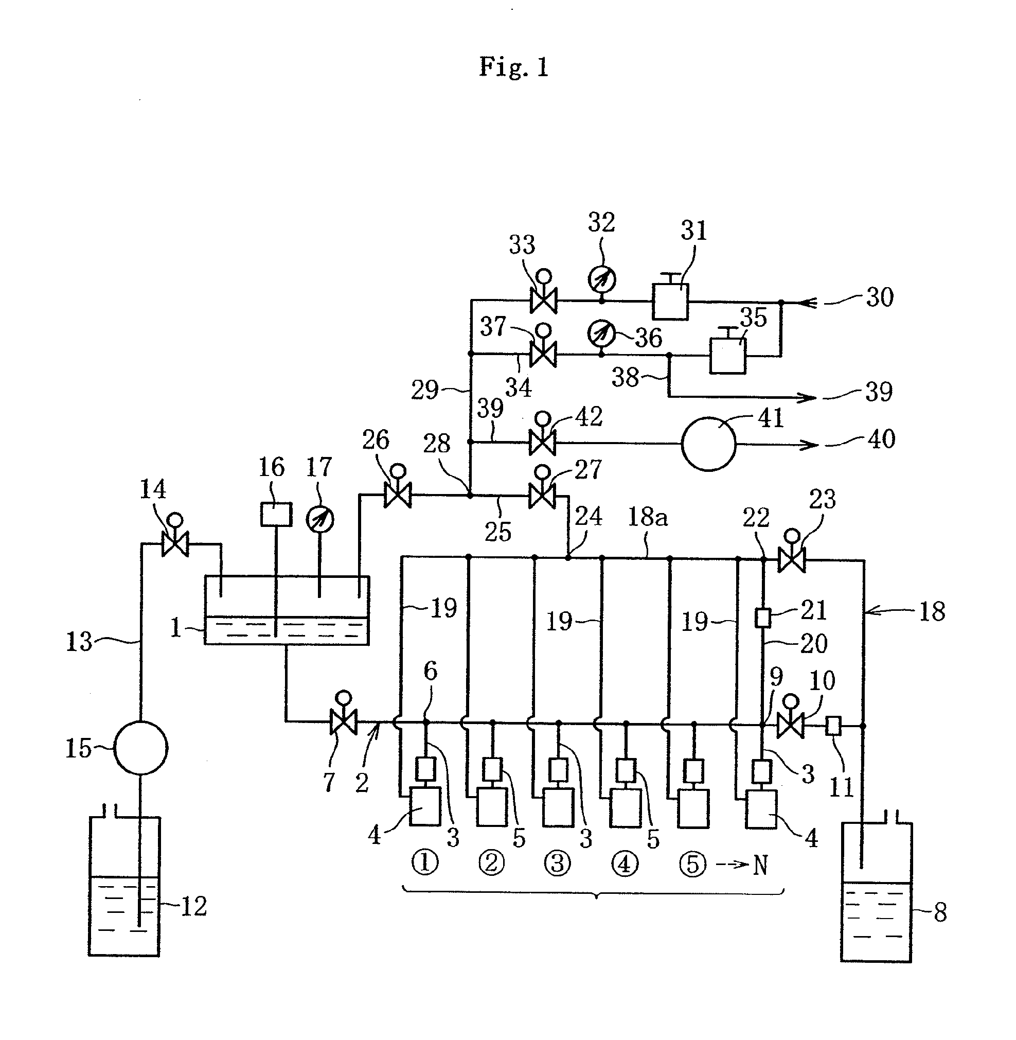
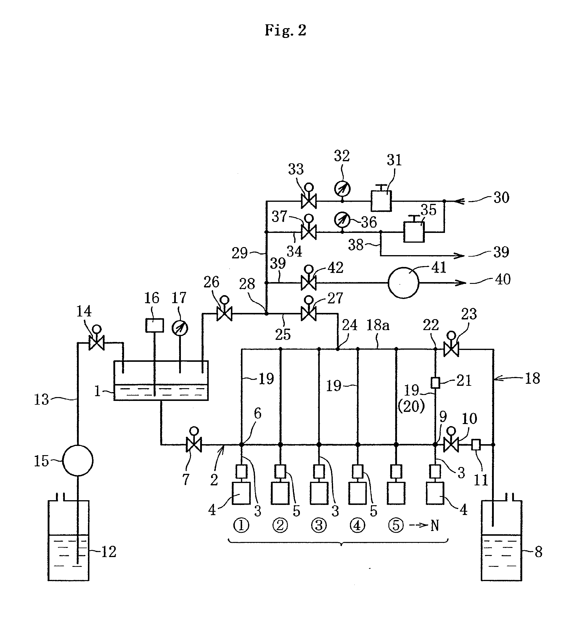
[0119]FIG. 2 illustrates a liquid feeding device for inkjet heads according to a second embodiment of the present invention. The liquid feeding device for inkjet heads of the second embodiment is different from the liquid feeding device for inkjet heads of the first embodiment in that each lower end of the separate gas flow pipe lines 19 extending downward from the bypass pipe line 18a of the common gas flow pipe line 18 communicates with each connection portion between the common liquid feed pipe line 2 and each of the separate liquid feed pipe lines 3, and in that the separate gas flow pipe line 19 provided on the lowermost downstream end also functions as the liquid feed gas flow pipe line 20. The other components of the liquid feeding device for inkjet heads according to the second embodiment are the same as those of the liquid feeding device for inkjet heads of the first embodiment, so the components common to those devices are denoted by the same reference symbols, and redunda...

third embodiment

[0122]FIGS. 3 to 5 each illustrate a liquid feeding device for inkjet heads according to a third embodiment of the present invention. As illustrated in FIG. 3, the liquid feeding device for inkjet heads according to the third embodiment includes a liquid feed path 3 for feeding the liquid material to an inkjet head 2 (liquid pool provided inside thereof) from the ink tank 1 storing the liquid material, and a first deaerating unit 4 and a second deaerating unit 5 provided at two positions halfway on the liquid feed path 3. The liquid feed path 3 is formed by connecting two deaerating tubes (hereinafter, referred to as “first deaerating tube 6 and second deaerating tube 7”) and three liquid feed tubes (hereinafter, referred to as “first liquid feed tube 8, second liquid feed tube 9, and third liquid feed tube 10”) to one another. Each of the first deaerating tube 6 and the second deaerating tube 7 has gas permeability, and is made of a synthetic resin, in which a single internal flow ...


PUM


Abstract

When liquid materials are fed to inkjet heads, fluid pressures of liquid materials to be fed to inkjet heads are equalized so that a gas does not remain in liquid feed pipe lines without causing structures of the liquid feed pipe lines to be complicated. Separate liquid feed pipe lines (3) for feeding the liquid material, each of which communicates with each of a plurality of inkjet heads (4), are each connected to a common liquid feed pipe line (2) which stores one kind of the liquid material and communicates with an ink tank (1). Separate gas flow pipe lines (19), each of which is capable of feeding a gas and communicates with a connection portion between the common liquid feed pipe line (2) and each of the separate liquid feed pipe lines (3), with each of the inkjet heads (4), or with both the connection portion and each of the inkjet heads (4), are each connected to a bypass pipe line (18a) (common gas flow pipe line (18)) capable of being opened and closed with respect to the atmosphere.

Description

TECHNICAL FIELD[0001]The present invention relates to a liquid feeding device for inkjet heads which is structured such that a liquid material is fed to inkjet heads from an ink tank, and to an inkjet head wiping device which is used to appropriately wipe and remove a foreign matter attached to a liquid material ejection port of each of inkjet heads and the vicinity thereof.BACKGROUND ART[0002]In recent years, a so-called inkjet method using an inkjet head has been widely employed in a case of performing printing using ink on a print medium such as paper, in a case of forming an orientation film or applying UV ink onto a substrate (transparent substrate) of a liquid crystal display device or the like, or in a case of applying a color filter onto a substrate of an organic EL display device.[0003]An inkjet printer (hereinafter including an oriented film forming device and a coating device) employing the inkjet method is provided with a liquid feeding device for feeding a liquid materi...

Claims


Application Information

Patent Timeline
Patent Type & Authority Applications(United States)
IPC IPC(8): B41J2/175
CPCB41J2/175B41J2/16585
Inventor NAKANO, TERUYUKIKOZAWA, YASUHIRO
Owner ISHII HYOKI
Why Eureka
Try Eureka