Image processing device and image processing method

Inactive Publication Date: 2011-01-20
SONY CORP
View PDF6 Cites 9 Cited by
  • Summary
  • Abstract
  • Description
  • Claims
  • Application Information

AI Technical Summary

Benefits of technology

[0020]According to the embodiment of the invention, on the computer graphics image obtained by mapping the texture map image to the surface of the texture map target, the superimposition image is superimposed at a position correspo

Problems solved by technology

When the character string by superimposition is inserted into an image which is texture mapped to a surface of the CG object, the character string becomes difficult to be read depending on a situation for the texture mapped face, for example, when the text mapped face is

Method used


Image

  • Image processing device and image processing method
  • Image processing device and image processing method
  • Image processing device and image processing method

Examples


first embodiment

1. First Embodiment

Configuration of an Image Processing Device

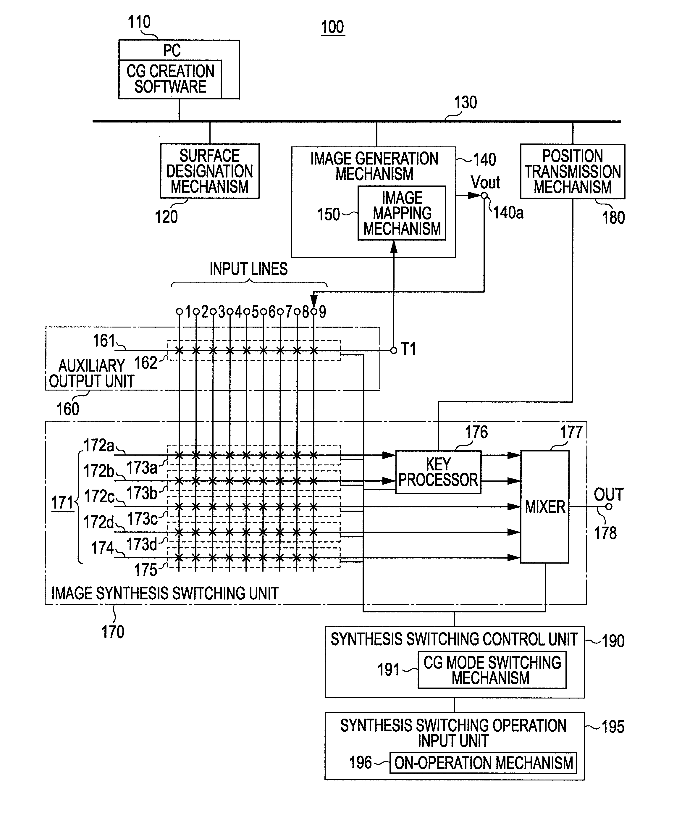
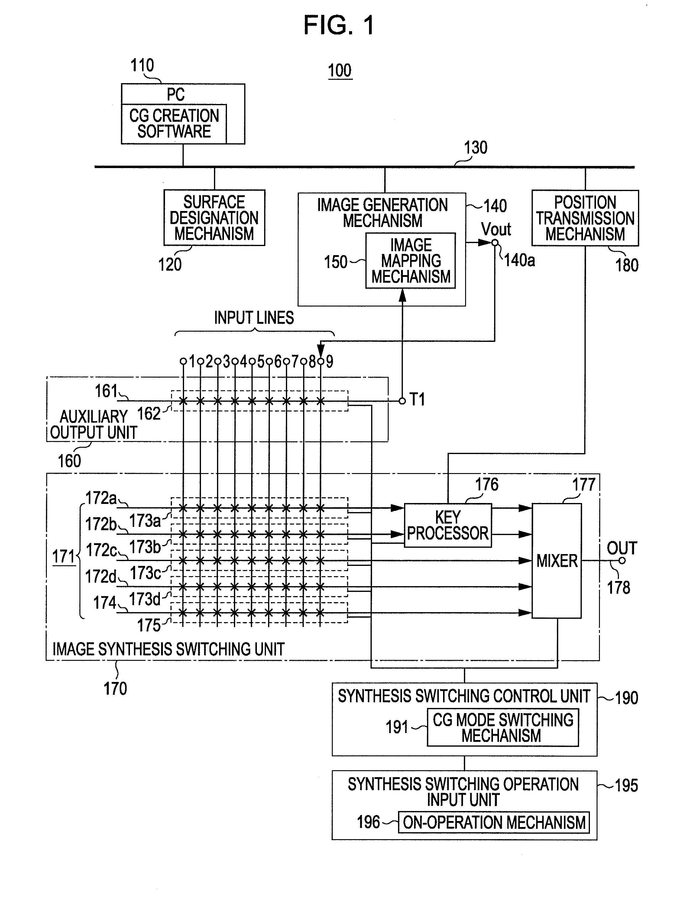
[0055]A first embodiment of the invention will be described. FIG. 1 shows a configuration example of an image processing device 100 according to the first embodiment. The image processing device 100 includes a CG (computer graphics) creation mechanism 110, a surface designation mechanism 120, a network 130, an image generation mechanism 140, and an image mapping mechanism 150. Also, the image processing device 100 includes an auxiliary output unit 160, an image synthesis switching unit 170, a position transmission mechanism 180, a synthesis switching control unit 190, and a synthesis switching operation input unit 195. The CG creation mechanism 110, the surface designation mechanism 120, the image generation mechanism 140, and the position transmission mechanism 180 are respectively connected to the network 130.

[0056]The CG creation mechanism 110 is constituted by a PC (personal computer) installed with CG creation softwa...

second embodiment

2. Second Embodiment

Configuration of an Image Processing Device

[0147]The second embodiment of the invention will be described. FIG. 13 shows a configuration example of an image processing device 100A according to the second embodiment. In FIG. 13, the same reference numerals are given to the elements corresponding to FIG. 1 and the description thereof will be omitted selectively.

[0148]The image processing device 100A includes a CG creation mechanism 110, a surface designation mechanism 120A, a network 130, an image generation mechanism 140A, and an image mapping mechanism 150A. Also, the image processing device 100A includes a matrix switch 210, an image selection operation mechanism 230, and a superimposition mechanism 240. The CG creation mechanism 110, the surface designation mechanism 120A, the image generation mechanism 140A, and the image selection operation mechanism 230 are respectively connected to the network 130.

[0149]The CG creation mechanism 110 is constituted by a PC (...

third embodiment

3. Third Embodiment

Configuration of an Image Processing Device

[0214]The third embodiment of the invention will be described. FIG. 22 shows a configuration example of an image processing device 100B according to the third embodiment of the invention. In FIG. 22, the same reference numerals are given to the elements corresponding to FIG. 1 and the description thereof will be omitted selectively.

[0215]The image processing device 100B includes a CG creation mechanism 110, a surface designation mechanism 120B, a network 130, an image generation mechanism 140B, and an image mapping mechanism 150B. Also, the image processing device 100B includes an auxiliary output nit 160B, an image synthesis switching unit 170B, a position transmission mechanism 180B, a synthesis switching control unit 190, and a synthesis switching operation input unit 195. The CG creation mechanism 110, the surface designation mechanism 120B, the image generation mechanism 140B, and the position transmission mechanism ...


PUM


Abstract

An image processing device includes an image generation mechanism configured to generate computer graphics images based on computer graphics description data, an image mapping mechanism configured to designate an object or a part of the object of computer graphics drawn by the image generation mechanism as a texture map target, and to texture map texture map images to a surface of the texture map target, and a superimposition mechanism configured to superimpose superimposition images at a position corresponding to the texture map target of the computer graphics images where the texture map has been performed in the image mapping mechanism, based on position information for the texture map target of the computer graphic image.

Description

BACKGROUND OF THE INVENTION[0001]1. Field of the Invention[0002]The present invention relates to an image processing device and an image processing method, and more particularly, to an image processing device or the like which performs an image synthesis by texture mapping an image by image data to computer graphics images.[0003]2. Description of the Related Art[0004]In a three-dimensional graphics system, an image's entirety is drawn by decomposing three-dimensional coordinates into polygons such as triangles and drawing the polygons. Therefore, in this case, the three-dimensional image can be said to be defined by the combination of the polygons. Meanwhile, surfaces of ambient things have many repetitive patterns of complicated shapes, and the shapes or the patterns are complicated and detailed, and thus it is difficult to model each shape or pattern as a triangle or the like. Therefore, as a means for solving this, a texture map can be used.[0005]The texture map realizes an image...

Claims


Application Information

Patent Timeline
IPC IPC(8): G09G5/00
CPCG06T15/04
Inventor NAKAMURA, SENSABUROOZAKI, NORIMASAUGAI, TAKEOKAKIHARA, TOSHIMASA
Owner SONY CORP
Why Eureka
Try Eureka