Rotating Electrical Machine

a technology of rotating electrical machines and rotating shafts, which is applied in the direction of synchronous machines, windings, dynamo-electric components, etc., can solve the problems of difficult to obtain any further increase of efficiency and worse control responsiveness of coil currents, and achieve excellent rotational characteristics and compactness of rotating electrical machines. , the effect of increasing efficiency

Active Publication Date: 2011-02-03
HITACHI LTD
View PDF2 Cites 17 Cited by
  • Summary
  • Abstract
  • Description
  • Claims
  • Application Information

AI Technical Summary

Benefits of technology

[0016]While maintaining the advantage of a distributed winding stator of possessing excellent rotational characteristics, it is possible to make this rotating electrical machine more compact and to increase its efficiency.

Problems solved by technology

However, since the technique described above is theoretically a concentrated winding, in the interlinkage magnetic flux with the rotor, the stator coil for each one phase only takes advantage of a 120° region of electrical angle, and this is in contrast to a distributed winding with which the entire 360° region of electrical angle is taken advantage of, and accordingly it becomes difficult to obtain any further increase of efficiency.
Due to this, in a generator, the amount of current generated in the high rotational speed region is held down, and, in a motor, while in a motor, the control responsiveness of the coil currents becomes worse.

Method used


Image

  • Rotating Electrical Machine
  • Rotating Electrical Machine
  • Rotating Electrical Machine

Examples


Embodiment Construction

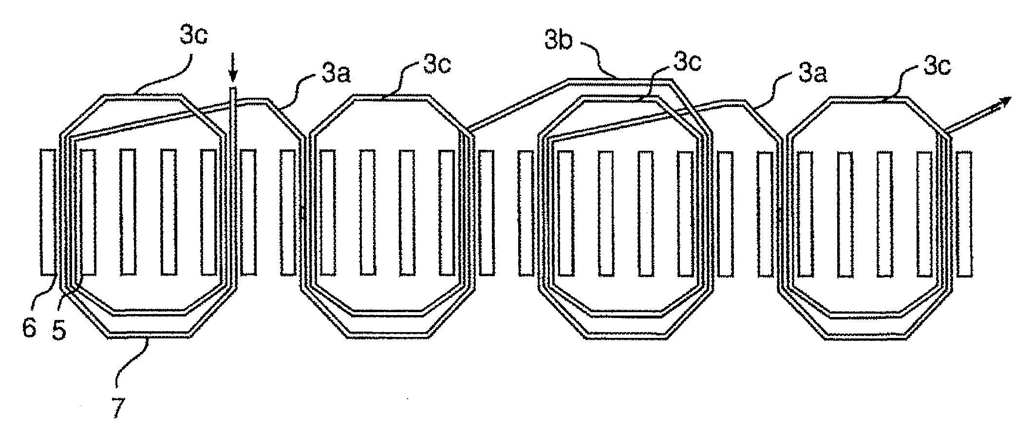
[0029]The embodiments explained below are related to a rotating electrical machine such as a motor or a generator or the like and to a method of manufacture thereof, and particularly relate to a rotating electrical machine that is equipped with a dispersal winding coil made by a thick wire lap winding method, and to a method of manufacture thereof.

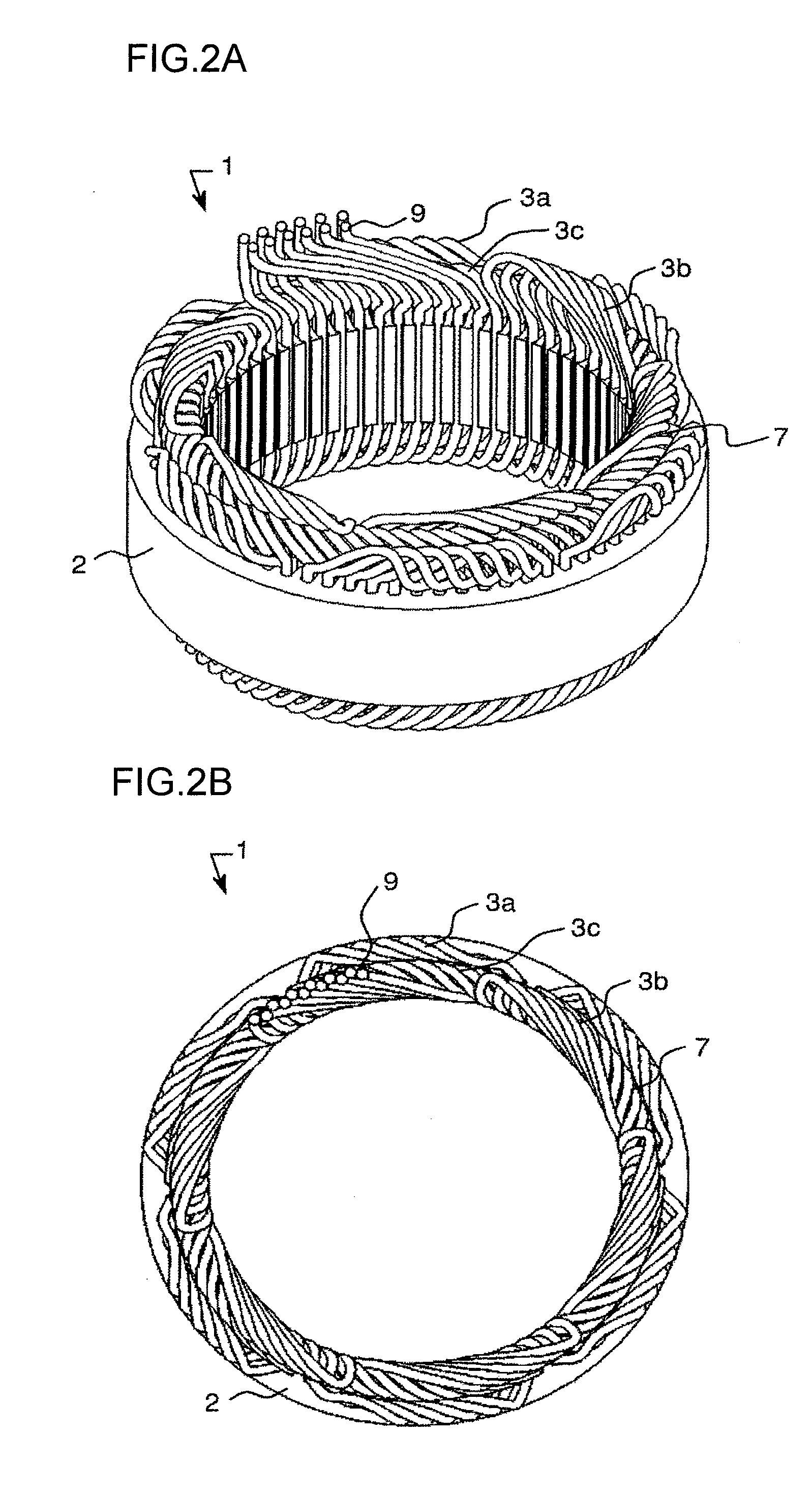
[0030]FIG. 1 shows a stator 1 according to the present invention, upon which coils are wound so that two stator magnetic poles formed by in-phase coils are disposed within 360° of electrical angle as defined by the magnetic poles of the rotor. In the following, a coil that has been made by this type of winding will be termed a “dispersal winding coil”.

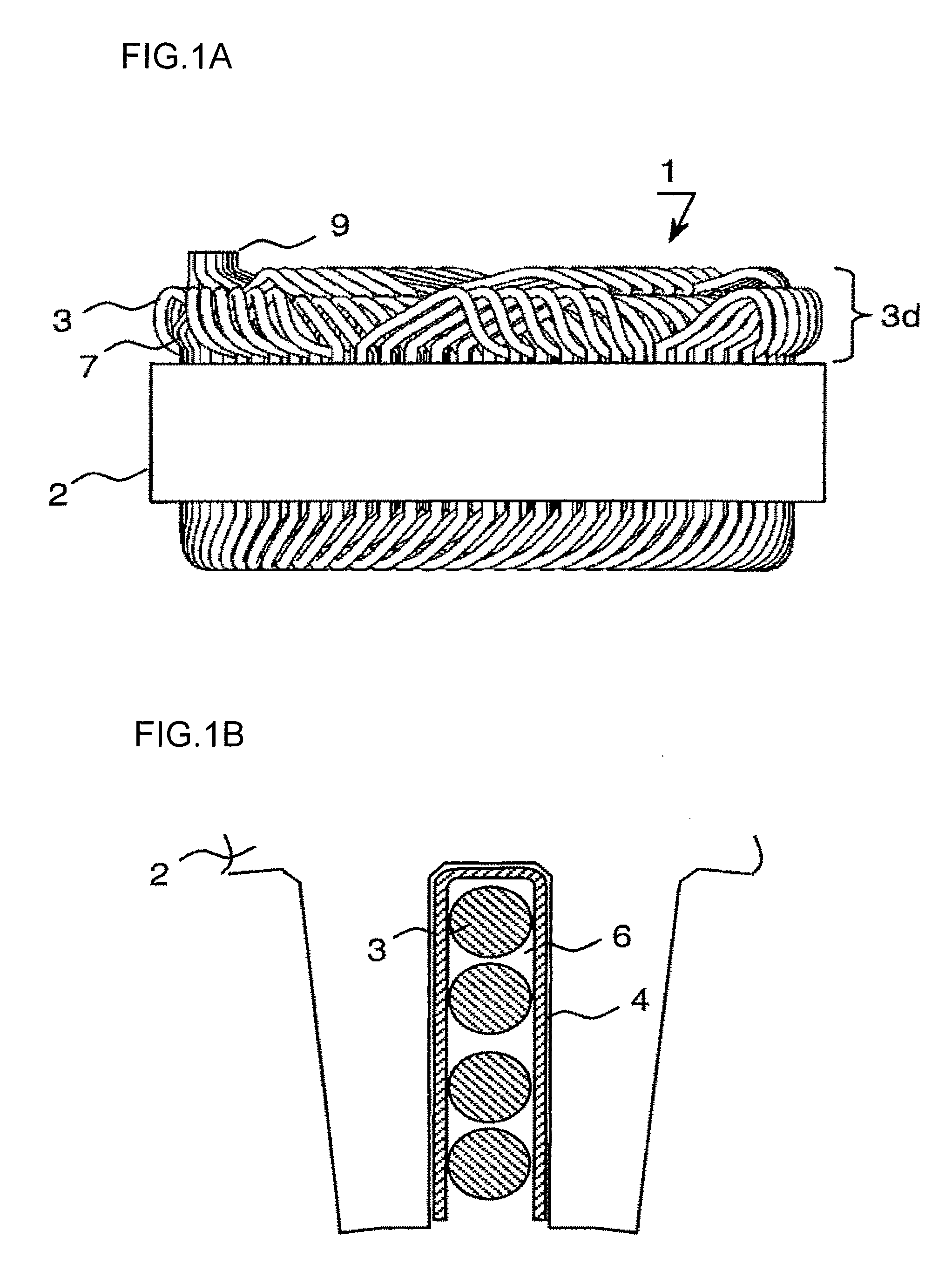
[0031]FIG. 1A is an elevation view showing this stator 1 as seen from its side: dispersal winding coils 7 are installed upon a stator core 2, and terminal portions 9 of wires 3 are connected thereto. With this structure, the height of the coil end portion 3d becomes low.

[0032]FIG. 1B is an en...


PUM


Abstract

A rotating electrical machine, includes; a rotor in which a plurality of magnetic poles are provided in circumferential direction, and a stator within the rotor is disposed with a gap against the rotor, wherein; two stator magnetic poles are formed by winding coils in phase and by the stator core within 360° of electrical angle defined by the magnetic poles of the rotor; the coil turns that form respective stator magnetic poles have angular widths in circumferential direction of less than 180° of electrical angle; the coil turns that form the respective two stator magnetic poles are provided so as not to mutually overlap and are wound so that adjacent ones of the stator magnetic poles have mutually opposite polarities, and; in the stator, each winding of each coil consists of an external bridge wire, a turn portion, an internal bridge wire, and a turn portion in that order.

Description

INCORPORATION BY REFERENCE[0001]The disclosure of the following priority application is herein incorporated by reference: Japanese Patent Application No. 2009-178581 filed Jul. 31, 2009.BACKGROUND OF THE INVENTION[0002]1. Field of the Invention[0003]The present invention relates to a rotating electrical machine.[0004]2. Description of the Related Art[0005]The methods of distributed winding and concentrated winding and so on are per se known as methods for constructing the stator coils of a rotating electrical machine. Among these, a winding construction is per se known (refer to Japanese Laid-Open Patent Publication H06-165422) that comprises a first three-phase connected coil in which three stator coils are wound upon the teeth of a stator core in a short-pitch lap winding at the magnetic pole pitch of a rotor and are three-phase connected, and a second three-phase connected coil in which three stator coils are wound upon the teeth of the stator core in a short-pitch lap winding, e...

Claims


Application Information

Patent Timeline
Patent Type & Authority Applications(United States)
IPC IPC(8): H02K3/28
CPCH02K19/34H02K3/28
Inventor NAGANAWA, TAKASHIMIYATA, KENJIISHIGAMI, TAKASHIISHIKAWA, YOSHIHISA
Owner HITACHI LTD
Why Eureka
Try Eureka