Orthosis

a technology of rigidity and orthosis, which is applied in the field of orthosis, can solve the problems of patients losing the range of motion of their joints, and the inability to use an orthosis that allows this type of movement, so as to prevent the loss of range of motion, impede joint movement, and inhibit wrist movemen

Active Publication Date: 2011-03-17
BLAKE MFG
View PDF11 Cites 28 Cited by
  • Summary
  • Abstract
  • Description
  • Claims
  • Application Information

AI Technical Summary

Benefits of technology

[0011]The present application is directed toward an orthosis having a dynamic flexible stiffener that is configured to extend across a joint and impede joint movement caused by muscle contractions by resisting flexing but allowing some movement in the joint. The stiffener is elastic so that it rebounds to its original form after flexing due to movement of the joint. The orthosis may be used to impede the movement of any joint. Preferably, however, the orthosis is designed to impede movement of the wrist and finger joints, the elbow joint, the knee joint, the hip joint, or the ankle and toe joints by having the flexible stiffener extend across the respective joint. Be...

Problems solved by technology

Patients that have neurological disorders such as cerebral palsy and multiple sclerosis, muscular disorders, stroke victims, or persons with spinal cord injuries often uncontrollably contract their joints i...

Method used


Image

  • Orthosis
  • Orthosis
  • Orthosis

Examples


first embodiment

sis

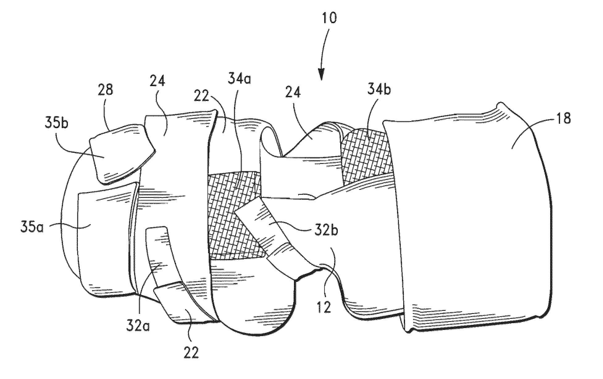
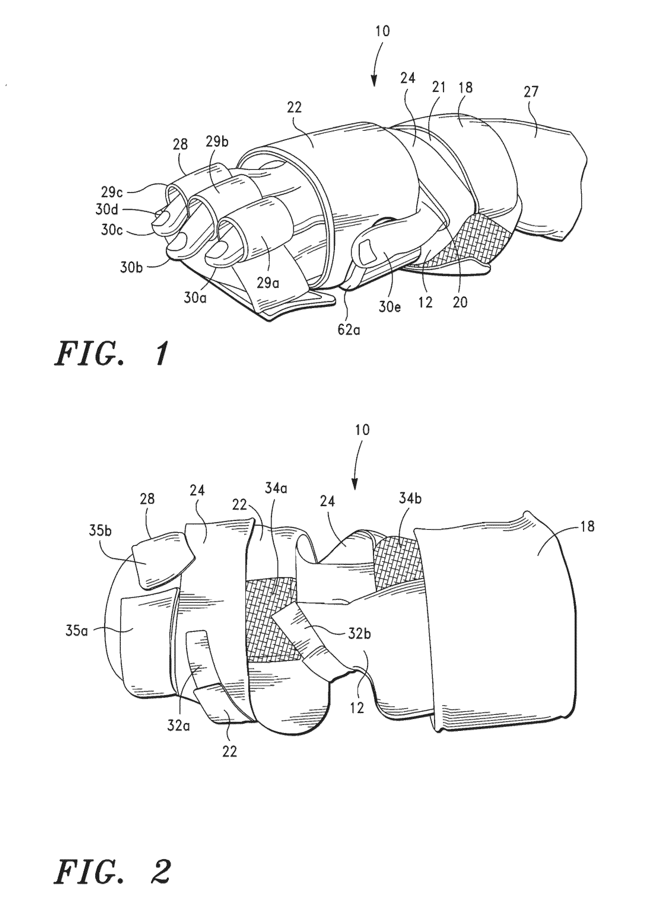
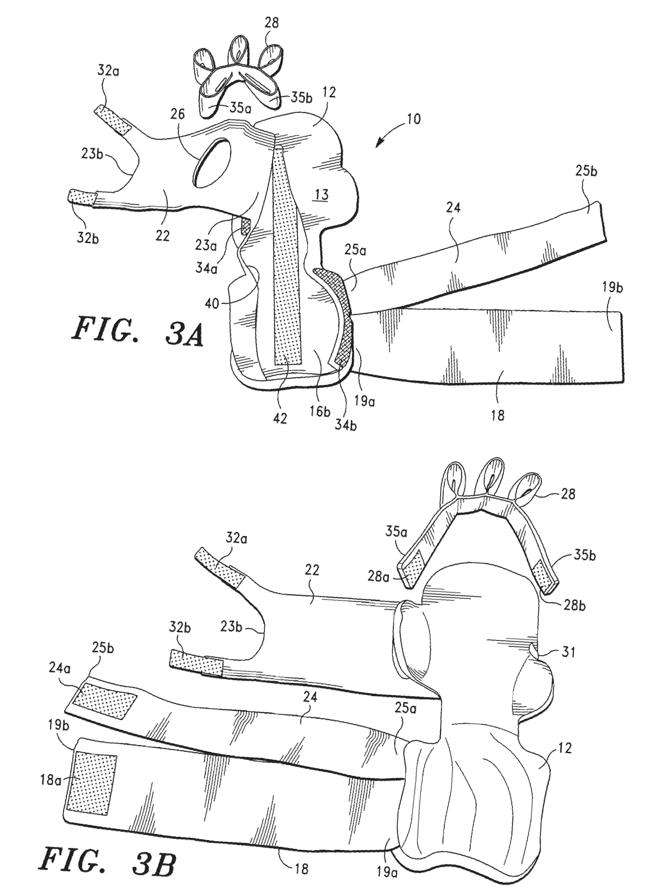
[0040]FIGS. 1-7 illustrate an orthosis for the hand and wrist in accordance with a first embodiment of the present invention. The hand and wrist orthosis 10 has a cover 12 (FIG. 1). a flexible stiffener 14 (FIGS. 5 & 6), which is positioned inside the cover, and opposed sheets 16a and 16b (FIG. 4), which encase the stiffener 14 for comfort. Cover 12 and opposed sheets 16a and 16b each have a shape that corresponds with the shape of stiffener 14. As shown in FIGS. 1-3C, a wrist strap 18 and one or more hand straps 22 and 24 are joined to cover 12 for securing a hand 20 and wrist 21 to the cover and stiffener. Further, a finger retainer 28 is joined to the cover and has a plurality of loops 29a, 29b, and 29c that respectively receive fingers 30a, 30b, and 30c in order to secure them to the cover. The loops 29a, 29h, and 29c are preferably spaced so that the fingers may alternatively reside between adjacent loops. Hand 20 also has a pinkie finger 30d resting on the top of cover 12 a...

second embodiment

[0059]Referring now to FIGS. 9-11, a foot orthosis in accordance with a second embodiment of the present invention is shown as 100. The foot orthosis has an L-shaped splint 102 with a first end 104 positioned adjacent to a posterior lower leg 106 and an opposite heel end 108 positioned underneath a heel 110. A flexible stiffener 112, shown in FIGS. 10 and 11, is joined to the heel end 108 of the splint. Preferably the stiffener is joined using a retaining clip 114 and one or more rivets 116a, 116b, and 116c. As shown in FIG. 9, the stiffener is positioned underneath foot 113 and toes, one of which is identified as 115, to impede downward movement of the foot and / or toes.

[0060]Referring to FIG. 11, retaining clip 114 is U-shaped with two legs 115a and 115b each having a free end 114a and a joined end 114b. The distance between the free ends 114a of the legs 115a and 115b is slightly greater than the combined thickness of the heel end 108 of the splint and the stiffener 112. When the ...

third embodiment

[0066]FIGS. 12-15 show an elbow orthosis 200 in accordance with a third embodiment of the present invention. The elbow orthosis has a tubular brace 202 that receives an arm 204 and extends across an elbow (not shown) from an upper arm 204a to a forearm 204b. As shown in FIGS. 13B and 13C, hook material 203a and 203b (FIG. 13B) is stitched to the inner surface of brace 202, and loop material 205a and 205b (FIG. 13C) is stitched to the outer surface of the brace. To secure the brace 202 to arm 204 the arm 204 is positioned over brace 202 so that the medial side of the elbow (not shown) is adjacent to the hole 202a shown in FIG. 13B. Then the brace 202 is wrapped around the arm 204 so that the hook material 203a and 203b engages the loop material 205a and 205b, respectively.

[0067]The brace also has one or more adjustable upper and lower straps 206a and 206b to secure the brace to arm 204. As shown in FIG. 13A, upper strap 206a has one end 207a that is stitched to brace 202 and a second...


PUM


Abstract

An orthosis comprising a dynamic, flexible, elastic stiffener that is configured to extend across a joint. The stiffener is configured to extend across a joint in a first configuration, wherein the stiffener is preferably substantially planar, and a second configuration when a patient's muscle is under contraction such that the stiffener allows some joint movement but resists flexion of the joint to impede joint movement. The stiffener rebounds to its first configuration after the muscle contraction has terminated. The orthosis may be used to impede the movement of any joint, including a wrist joint and finger joints, an elbow joint, a knee joint, and an ankle joint and toe joints. Preferably, the flexible stiffener is made from a heat treated and tempered spring steel so that is has desirable dynamic and elastic properties.

Description

CROSS-REFERENCE TO RELATED APPLICATIONS[0001]Not applicable.STATEMENT REGARDING FEDERALLY SPONSORED RESEARCH OR DEVELOPMENT[0002]Not applicable.BACKGROUND OF THE INVENTION[0003]1. Field of the Invention[0004]The present application is directed to an orthosis and, more specifically, to an orthosis having a flexible stiffener.[0005]2. Description of Related Art[0006]Patients that have neurological disorders such as cerebral palsy and multiple sclerosis, muscular disorders, stroke victims, or persons with spinal cord injuries often uncontrollably contract their joints in flexion, which can cause the patients to lose range of motion in their joints. Common joints that are affected by patients having these conditions include wrist joints and finger joints, foot, toe, and ankle joints, hip joints, elbow joints, and knee joints. In an attempt to treat or otherwise alleviate the potential loss of range of motion due to conditions like those set forth above, doctors and physical therapists o...

Claims


Application Information

Patent Timeline
IPC IPC(8): A61F5/00
CPCA61F5/0106A61F5/0118A61F5/05841A63B21/1446A61F5/0102A63B21/1403A63B21/055A63B23/035A61F5/0104A63B21/02A63B21/4023A63B21/4001
Inventor PRICE, STEPHEN A.PRICE, MARY P.
Owner BLAKE MFG
Why Eureka
Try Eureka