Air suspension

a technology of air springs and air tubes, which is applied in the direction of shock absorbers, mechanical devices, transportation and packaging, etc., can solve the problems of forming cracks in the damper bush, affecting the performance of air springs, so as to prevent damage and/or failure of components.

Inactive Publication Date: 2011-05-05
HL MANDO CORP
View PDF10 Cites 4 Cited by
  • Summary
  • Abstract
  • Description
  • Claims
  • Application Information

AI Technical Summary

Benefits of technology

[0013]The present disclosure is directed to solving the problems of the related art, and an aspect of the present disclosure provides an improved air suspension that prevents damage and/or

Problems solved by technology

Conventionally, the air suspension has a problem in that components of the air spring, in particular, an air sleeve and/or an air tube, are highly susceptible to damage due to vertical movement, torsional rotation and upward tilt (that is, coning angle) applied to the air spring during steering.
This problem is common to both canister insert-molded integration type and canister/upper mount separation type air suspensions.
In the former case, for example, when steering a 5-link double wishbone type vehicle, the variation in kingpin axis causes the up-down movement, torsional rotation and coning

Method used


Image

  • Air suspension
  • Air suspension
  • Air suspension

Examples


Embodiment Construction

[0020]Hereinafter, exemplary embodiments of the present disclosure will be described in detail with reference to the accompanying drawings. Like elements will be denoted by like reference numerals throughout the specification and drawings.

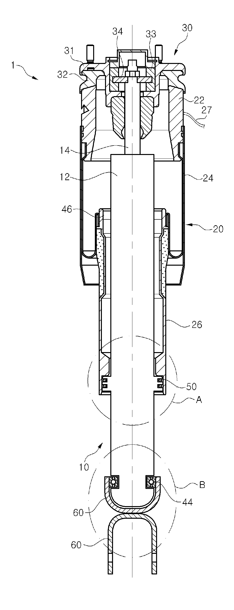
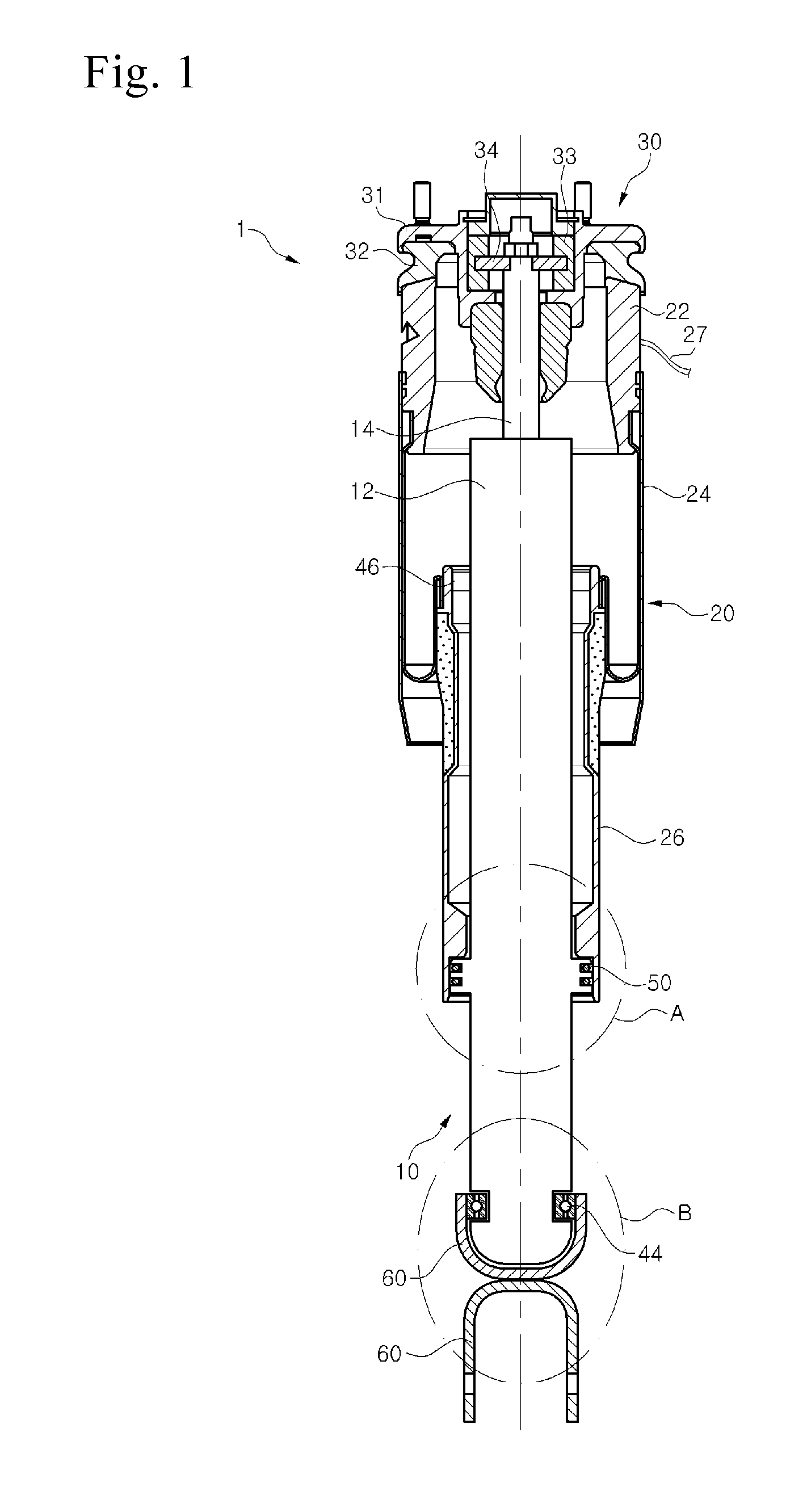
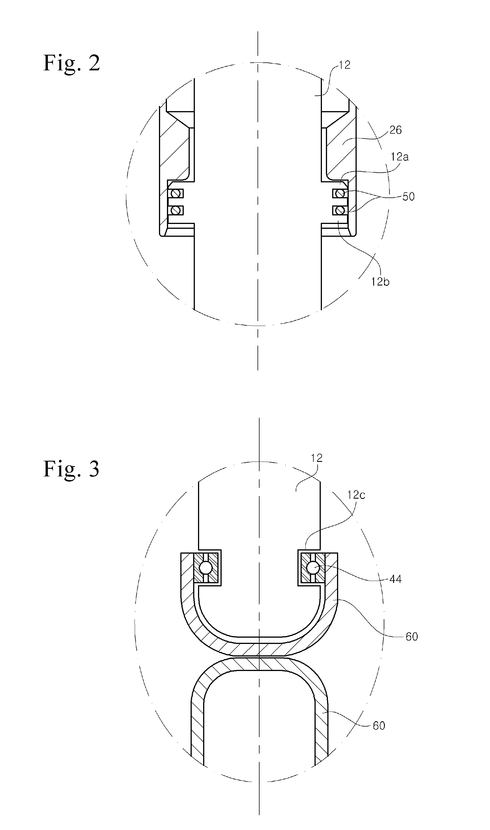
[0021]FIG. 1 is a side-sectional view of an air suspension in accordance with an exemplary embodiment, FIG. 2 is an enlarged view of part “A” of FIG. 1, and FIG. 3 is an enlarged view of part “B” of FIG. 1.

[0022]Referring to FIG. 1, an air suspension 1 according to this embodiment includes a damper 10, an air spring 20 mounted on the damper 10, and an upper mount 30 for connecting the damper 10 and air spring 20 to a vehicle frame (not shown). The damper 10 is provided at a lower side thereof with a bracket 60 which connects the air suspension to an axle or wheel side.

[0023]The damper 10 includes a cylinder 12 and a piston rod 14. Although not shown in the drawings, an elongated space filled with an oil is defined in the cylinder 12 and a piston va...


PUM


Abstract

Disclosed is an improved air suspension that prevents damage and/or failure of a component of an air spring, such as an air sleeve. The air suspension includes a damper including a cylinder and a piston rod slidably disposed in the cylinder, an air spring hermetically connected to an outside of the cylinder, an upper mount which secures the damper and the air spring to a vehicle frame, and a rotational sealing part disposed between the air piston and the cylinder and allowing relative rotation of the air spring and the cylinder while maintaining air-tightness between the air piston and the cylinder. The air suspension may prevent damage and/or failure of components of an air spring, such as an air sleeve, by undesired force or moment such as torsional rotational force applied to the air spring in the course of driving the vehicle.

Description

CROSS REFERENCE TO RELATED APPLICATION[0001]This application claims priority from and the benefit of Korean Patent Application No. 10-2009-0104873, filed on Nov. 2, 2009, which is hereby incorporated by reference for all purposes as if fully set forth herein.BACKGROUND[0002]1. Technical Field[0003]The present disclosure relates to an air suspension including a damper and an air spring, and, more particularly, to an air suspension which includes an improved structure to prevent damage of a component of an air spring, in particular, an air sleeve.[0004]2. Description of the Related Art[0005]In general, a suspension is disposed between a vehicle frame and wheels, and includes springs and dampers, that is, shock absorbers. A suspension system employing air springs is referred to as an “air suspension”. The air suspension includes an upper mount for securing both the damper and air spring to the vehicle frame.[0006]The damper includes a cylinder and a piston rod. The cylinder has a space...

Claims


Application Information

Patent Timeline
IPC IPC(8): B60G15/12F16F9/16F16F9/06
CPCB60G15/12B60G15/14F16F13/002F16F9/54F16F9/0454B60G13/06B60G13/10F16F9/34
Inventor JI, YOUNG CHUN
Owner HL MANDO CORP
Why Eureka
Try Eureka