Wire harness and method of manufacturing the same

Inactive Publication Date: 2011-06-30
HITACHI CABLE
View PDF4 Cites 9 Cited by
  • Summary
  • Abstract
  • Description
  • Claims
  • Application Information

AI Technical Summary

Benefits of technology

[0015]Therefore, it is an object of the invention to provide a wire harness that is capable of sufficiently maintaining air-tightness between a housing of a connector and a cable without melting a sheath of the cable as much as possible and a method of manufacturing the wire harness.

Problems solved by technology

However, the above-mentioned wire harness 121 has a problem described below.

Method used


Image

  • Wire harness and method of manufacturing the same
  • Wire harness and method of manufacturing the same
  • Wire harness and method of manufacturing the same

Examples


Embodiment Construction

[0063]The preferred embodiments according to the invention will be explained below referring to the drawings.

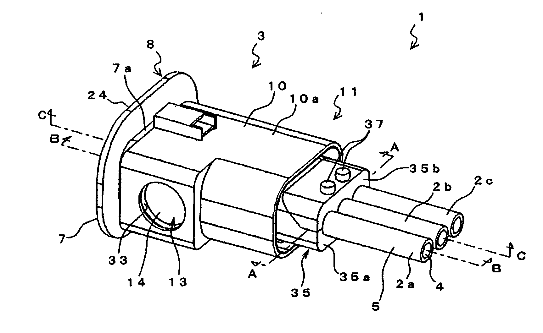
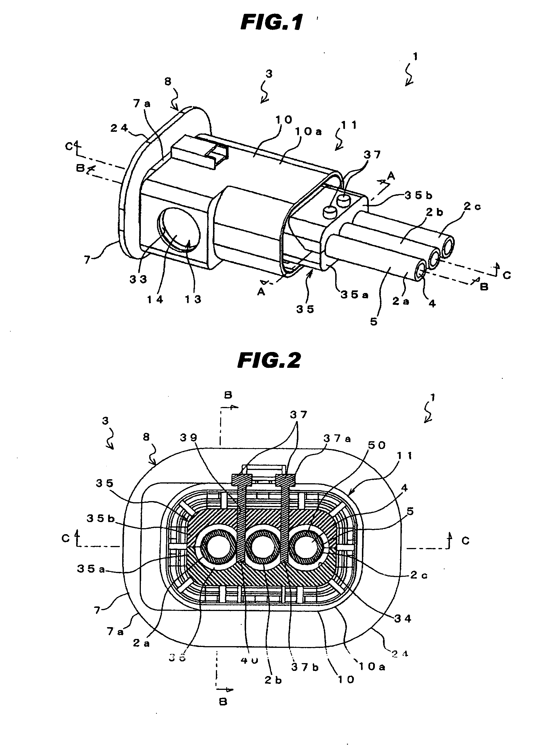
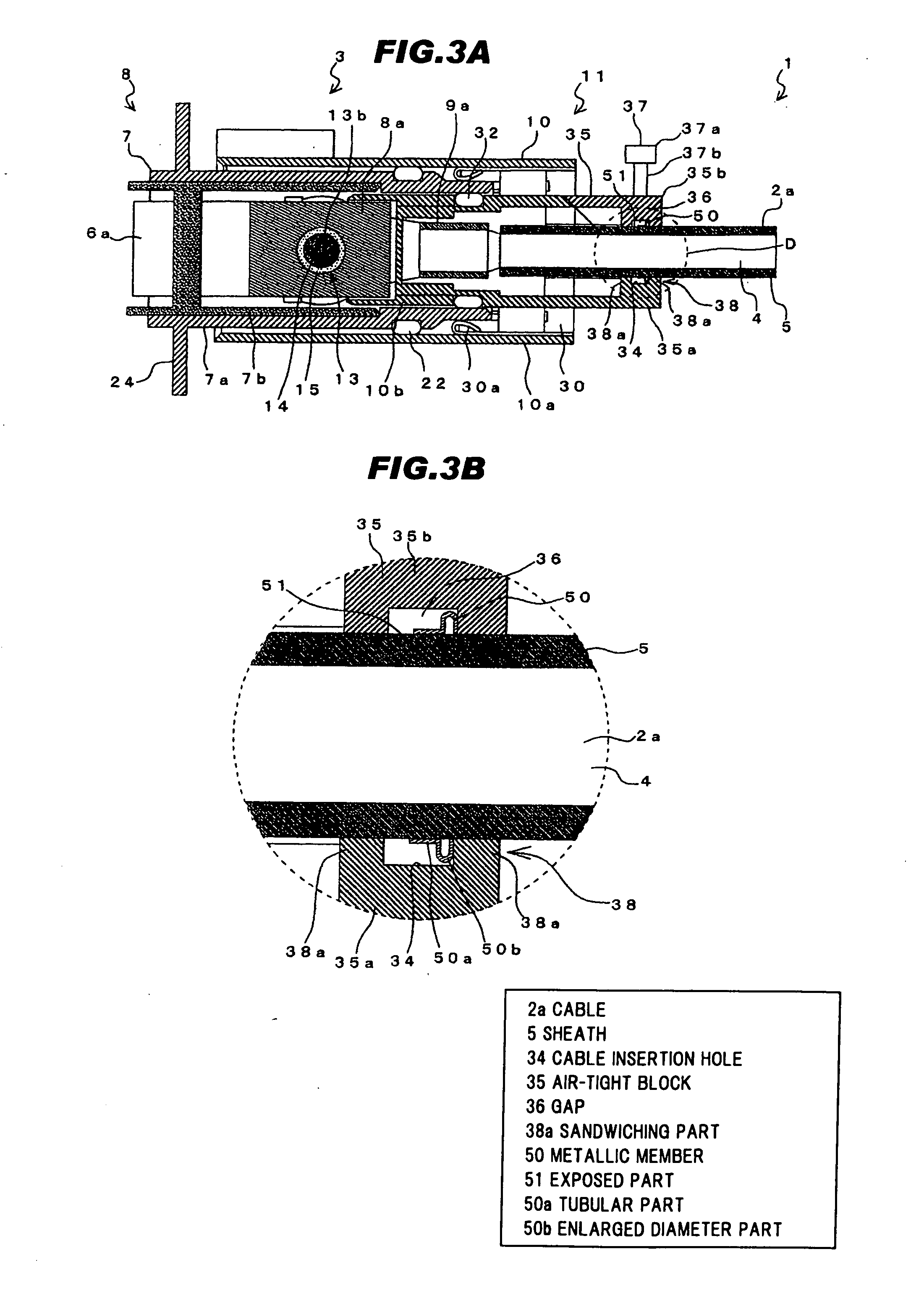
[0064]FIG. 1 is a perspective view schematically showing a wire harness according to one embodiment of the invention, FIG. 2 is a cross-sectional view taken along the line A-A in FIG. 1, FIG. 3A is a cross-sectional view taken along the line B-B in FIG. 1, FIG. 3B is an enlarged view of a part D of FIG. 3A, FIG. 4A is a cross-sectional view taken along the line C-C in FIG. 1, and FIG. 4B is an enlarged view of a part E of FIG. 4A. Further, the detail will be explained later, but FIG. 1 shows a state after a melting member 37 is melted and FIGS. 2 to 4 show a state before the melting member 37 is melted.

[0065]As shown in FIGS. 1 to 4, a wire harness 1 includes a plurality of cables 2a to 2c arranged in parallel and a connector 3 to which end portions of the cables 2a to 2c are connected.

[0066]The wire harness 1 is used for, for example, a connection between a motor of a hybrid...


PUM

PropertyMeasurementUnit
Forceaaaaaaaaaa
Lengthaaaaaaaaaa
Distanceaaaaaaaaaa

Abstract

A wire harness includes a plurality of cables arranged in parallel and a connector comprising a housing to which end portions of the plurality of cables are connected. The housing has an air-tight block at a side thereof that the plurality of cables are connected. The air-tight block further includes two closing parts for closing a space between the air-tight block and the cables at two places along a longitudinal direction of the cables, and for defining a part of a cable insertion hole. A metallic member protruding outwardly in a radial direction of the cables is fixed by swaging to a periphery of each of the cables between both of two closing parts for restricting a movement of the cables along the longitudinal direction in a pulling force or pressing force of the cables.

Description

[0001]The present application is based on Japanese patent application No. 2009-293347 filed on Dec. 24, 2009, the entire contents of which are incorporated herein by reference.BACKGROUND OF THE INVENTION[0002]1. Field of the Invention[0003]This invention relates to a wire harness that is capable of sufficiently maintaining air-tightness between a housing of a connector and a cable and a method of manufacturing the wire harness.[0004]2. Description of the Related Art[0005]Generally, in a wire harness used for vehicles etc., a water proof structure is installed between the housing of the connector and the cable in order to prevent water or the like from entering into the inside of the connector so as to cause a problem.[0006]A conventional wire harness 111 shown in FIGS. 11A and 11B uses a wire seal 114 as the air-tightness maintaining structure.[0007]The wire harness 111 is configured to maintain the air-tightness between the outer housing 113 of the connector 116 and the cable 112 b...

Claims


Application Information

Patent Timeline
IPC IPC(8): H01R13/58H01R43/00
CPCB60R16/0207H01R13/5205H01R13/5216H01R13/5804H01R13/5845H01R43/005H01R2201/26Y10S439/936Y10T29/49176H01R43/20H01R43/28
Inventor KATAOKA, YUTATAKEHARA, HIDEAKIFUKUDA, KUNIHIROSUZUKI, SACHIO
Owner HITACHI CABLE
Why Eureka
Try Eureka