Coolant reservoir tank for fuel cell vehicle

Active Publication Date: 2009-06-18
HYUNDAI MOTOR CO LTD +1
View PDF6 Cites 10 Cited by
  • Summary
  • Abstract
  • Description
  • Claims
  • Application Information

AI Technical Summary

Benefits of technology

[0018]Preferably, a cured silicon rubber is attached on the circumferential surface of the top portion of the reservoir housing to maintain air tightness between the cover and the reservoir housing.
[0019]Also preferably, the coolant reservoir tank may further comprise: a cap nut connected to a bottom portion of each of the ports; and at least one screw-type tube formed integrally with and protruding from a portion of the top surface of the cover and having a screw thread on the outer circumferential surface thereof. In this case, each of the ports is connected to the cover by connection between the cap nut and the screw-type tube. In this case, an O-ring may further be provided on a top portion of the screw-type tube to maintain air tightness between each of the ports and the cover.
[0020]Also suitably, the bottom surface of the reservoir housing is inclined toward the center of the bottom of the reservoir housing, a straight pipe is provided to extend vertically from the center, and a top portion of the straight pipe is to be inserted into one of the screw-type tubes provided on the cover such that coolant stored in the reservoir housing is introduced through a bottom portion of the straight pipe and moved upward by a pressure difference caused by a vacuum applied in a fuel cell. In this case, an O-ring may further be mounted on a top portion of the straight pipe to maintain air tightness between the pipe and the screw-type tube.

Problems solved by technology

However, the above-described structure has some drawbacks in that the assembling efficiency is deteriorated due to the large number of bolts 102 (approximately 80).
Moreover, during the startup of the fuel cell system, the vacuum state is not maintained in the system by the leakage of the connection portions, and thus the coolant may not be smoothly supplied to the system.
Furthermore, as shown in FIG. 4, a pipe 105 having a “C” shape provided in the reservoir housing 11, although it can suck the coolant at the bottom of the reservoir tank to enable coolant supply even if the vehicle is inclined on a slope, may cause a pressure drop, which prevents a smooth coolant supply even if the inside of the fuel cell system is under a vacuum condition.

Method used


Image

  • Coolant reservoir tank for fuel cell vehicle
  • Coolant reservoir tank for fuel cell vehicle
  • Coolant reservoir tank for fuel cell vehicle

Examples


Embodiment Construction

[0037]Reference will now be made in detail to the preferred embodiments of the present invention, examples of which are illustrated in the drawings attached hereinafter, wherein like reference numerals refer to like elements throughout. The embodiments are described below so as to explain the present invention by referring to the figures.

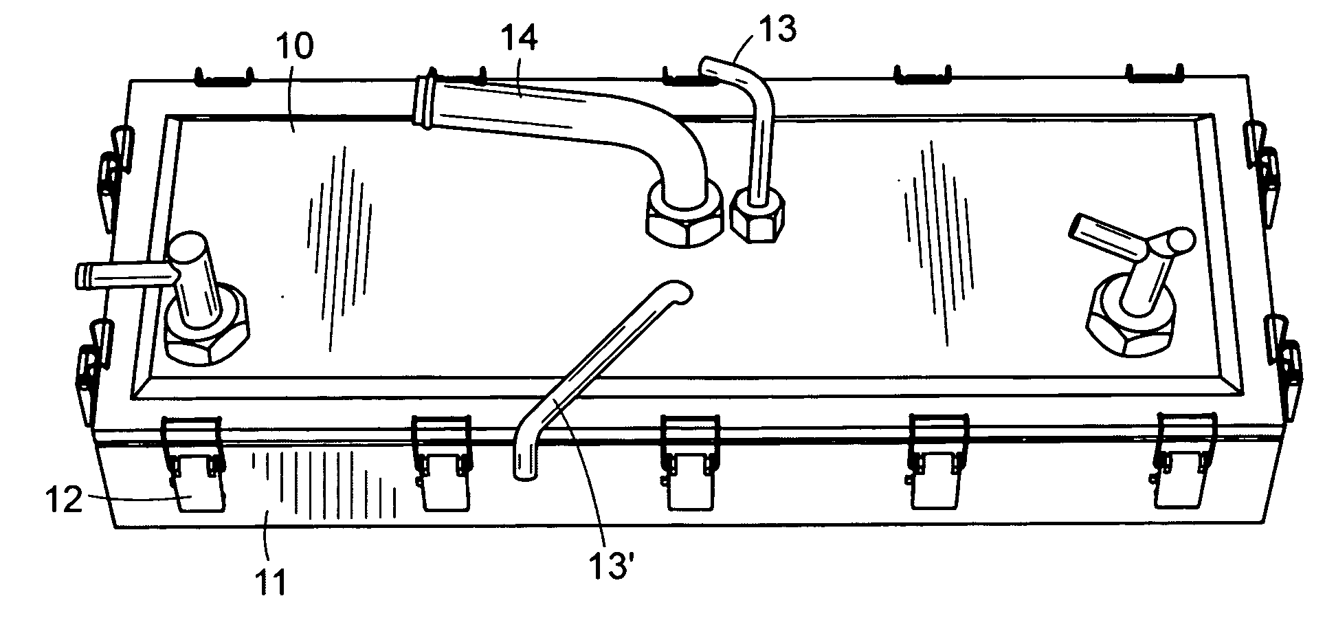
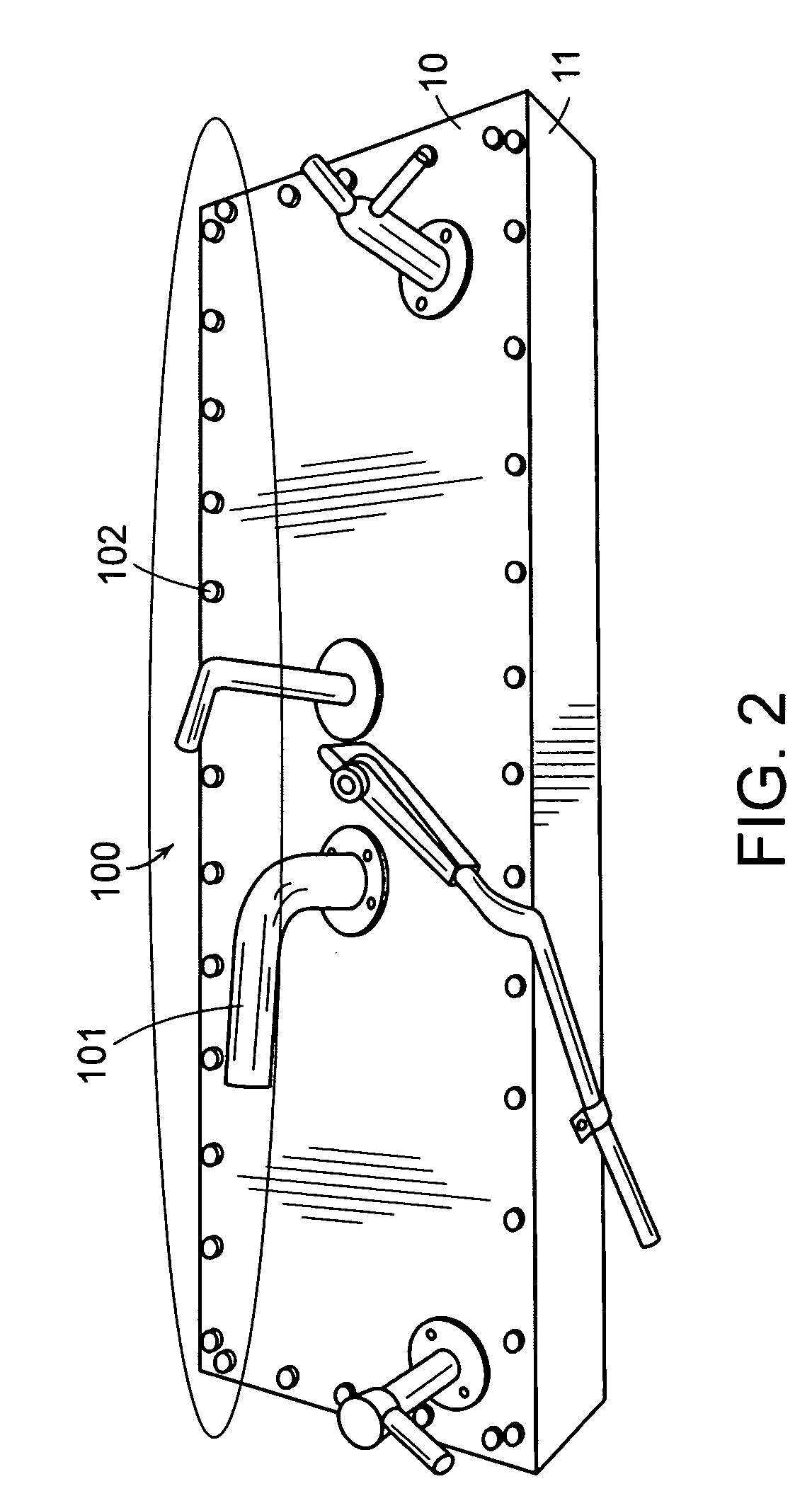
[0038]FIG. 5 is a diagram showing a coolant reservoir tank in accordance with a preferred embodiment of the present invention; FIG. 6 is a diagram showing a state before various ports of the coolant reservoir tank of FIG. 5 are connected; FIG. 7 is a diagram showing an internal structure of the coolant reservoir tank of FIG. 5; FIG. 8 is a diagram showing a bottom portion of the internal structure of FIG. 7; FIG. 9 is an exploded view of an outlet port and a screw-type tube of the coolant reservoir tank of FIG. 5; FIG. 10 is a diagram showing a portion of the coolant reservoir tank of FIG. 5 before a fastening member is fastened; and FIG. 11 is a di...


PUM


Abstract

The present invention provides a coolant reservoir tank for a fuel cell vehicle, in which the coolant reservoir tank is positioned at a bottom of the vehicle such that coolant in a coolant line is collected in the reservoir tank by gravity during shutdown of a fuel cell system and the coolant in the reservoir tank is supplied to the coolant line by a vacuum pump during startup of the fuel cell system.For this purpose, the present invention provides a coolant reservoir tank including: a coolant reservoir tank for a fuel cell vehicle, the coolant reservoir tank comprising: a reservoir housing having a predetermined volume of space; a cover for covering the top of the reservoir housing; and a plurality of ports detachably provided on at least one portion of the cover, wherein the reservoir housing and the cover are connected by a hinge type fastening member.

Description

CROSS-REFERENCE TO RELATED APPLICATION[0001]This application claims under 35 U.S.C. §119(a) the benefit of Korean Patent Application No. 10-2007-0130091 filed Dec. 13, 2007, the entire contents of which are incorporated herein by reference.BACKGROUND[0002](a) Technical Field[0003]The present invention relates to a coolant reservoir tank for a fuel cell vehicle. More particularly, the present invention relates to a coolant reservoir tank for a fuel cell vehicle, which is positioned at a bottom of the vehicle such that coolant in a coolant line is collected to the reservoir tank by gravity when a fuel cell system is inactivated and the coolant in the reservoir tank is supplied to the coolant line by a vacuum pump during startup of the fuel cell system.[0004](b) Background Art[0005]A fuel cell system generates electricity by converting chemical energy of fuel directly into electric energy. The fuel cell system generally comprises a fuel cell stack for generating electricity, a fuel sup...

Claims


Application Information

Patent Timeline
IPC IPC(8): F01P3/00
CPCB60K11/02H01M8/04029Y02E60/50Y02T90/32H01M2250/20Y02T10/70Y02T90/40Y10T137/86348Y10T137/86372Y10T292/0871B60K11/00F01P11/00H01M8/04
Inventor NA, SUNG WOOKHAN, SU DONG
Owner HYUNDAI MOTOR CO LTD
Why Eureka
Try Eureka