Suspended single push and pull energy-saving window

A technology for energy-saving windows and sliding windows, which is applied to door/window accessories, window/door frames, and wing leaf suspension devices, and can solve problems such as difficult airtightness, lack of practicability, and poor airtightness. Achieve good water tightness, solve the problem of poor air tightness and good dustproof effect

Active Publication Date: 2014-12-10
常州玖洲联横建材有限公司
View PDF5 Cites 0 Cited by
  • Summary
  • Abstract
  • Description
  • Claims
  • Application Information

AI Technical Summary

Problems solved by technology

However, the current external doors and windows, such as aluminum-wood broken bridge doors and windows, can only be made to open inward, or open inward and invert, and are not suitable as sliding windows.
Ordinary aluminum windows with broken bridges can only be made to open inward or inwardly, which lacks practicability and is relatively expensive.
Nowadays, many aluminum alloy sliding windows made of broken bridges are practical and convenient, but the airtightness is not good, and they do not meet the current energy-saving requirements and acceptance standards.
[0003] The existing sliding window tracks are all set at the lower part of the doors and windows. From a structural point of view, there is a cavity between the sealing track and the pulley, and the airtightness is difficult to guarantee.
In addition, for the existing external windows, the window sash is installed from the outside, and the waterproof baffle is on the inside of the window sash
In bad weather such as typhoon and rain, due to the large pressure difference between indoor and outdoor, rainwater will be pressed into the room from the original outlet and the track below, causing inconvenience and safety hazards

Method used


Image

  • Suspended single push and pull energy-saving window
  • Suspended single push and pull energy-saving window
  • Suspended single push and pull energy-saving window

Examples


Embodiment 1

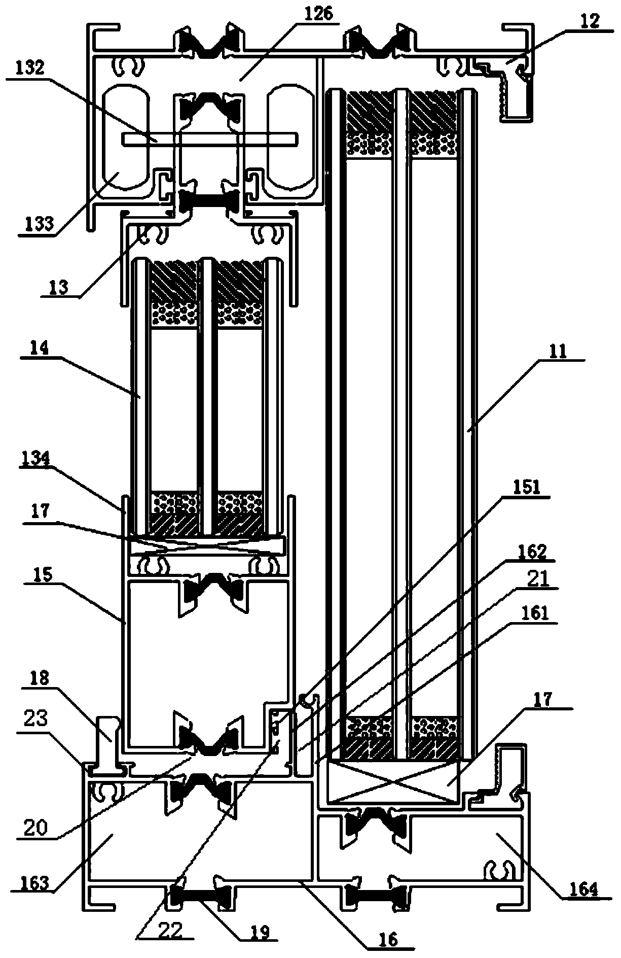
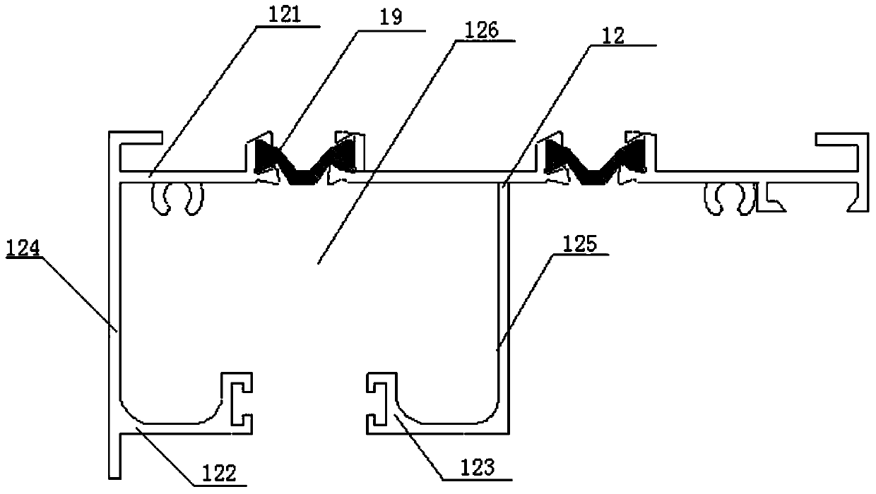
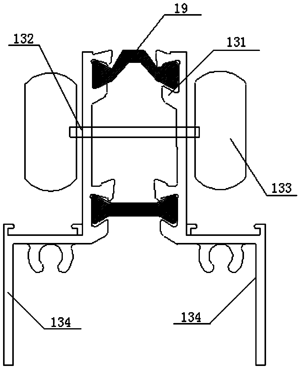
[0034] like figure 1 The structure diagram of the top-hung single push-pull energy-saving window shown in the present invention includes a fixed window 11, a window frame upper horizontal frame 12, an upper window frame 13, a sliding window 14, a lower window frame 15, and a lower window frame 16. The upper and lower ends of 11 are respectively fixed with the right side of the upper horizontal frame 12 of the window frame and the lower horizontal frame 16 of the window frame; a spacer 17 is arranged between the lower end of the fixed window 11 and the lower horizontal frame 16 of the window frame to play a better role. Ground sealing effect.

[0035] The sliding window 14 is arranged in parallel with the fixed window 11, and the upper and lower ends of the sliding window 14 are respectively fixed with the left side of the upper horizontal frame 12 of the window frame and the lower horizontal frame 16 of the window frame, and the lower end of the sliding window 14 is connected ...


PUM


Abstract

The invention discloses a suspended single push and pull energy-saving window. The arrangement position of a pulley is adjusted, the structure of the energy-saving window is changed, and the pulley is arranged at the upper position of the window. The problems that an existing push and pull window is not tight in sealing, so that the airtightness is poor, energy saving is not achieved are effectively solved, meanwhile, the dustproof effect is good, and cleaning is convenient. A wool bar and a rubber bar are arranged at the corresponding positions of the lower potion of the suspended single push and pull energy-saving window, the effects of dual sealing, heat insulation and water resistance are achieved. A rubber cushion layer arranged at the bottom of the suspended single push and pull energy-saving window is the further guarantee to the airtightness, and the dustproof effect is achieved. The push and pull window is mounted from an indoor position, and a waterproof baffle is arranged on the outer side of the push and pull window. The pressure formed in the poor weather condition only acts on an inner layer of baffle, the influence of air pressure is avoided, and good watertightness can be achieved.

Description

technical field [0001] The invention relates to an energy-saving window for buildings, in particular to a top-hung single push-pull energy-saving window. Background technique [0002] External doors and windows, especially the external windows are the eyes of the whole building, which should be beautiful, practical and convenient. However, the current external doors and windows, such as aluminum-wood broken bridge doors and windows, can only be made to open inwards, or open inwards and fall inwards, which are not suitable for sliding windows. Ordinary broken bridge aluminum windows can only be made to open inward or inwardly, which lacks practicality and is relatively expensive. Nowadays, many aluminum alloy sliding windows made of broken bridges are practical and convenient, but the airtightness is not good, and they do not meet the current energy-saving requirements and acceptance standards. [0003] Existing sliding window tracks are all arranged at the lower part of do...

Claims


Application Information

Patent Timeline
Patent Type & Authority Applications(China)
IPC IPC(8): E06B3/46E05D13/00E06B7/16E06B1/36E06B3/06E06B7/26
Inventor 王兴栋王洁刘文宇
Owner 常州玖洲联横建材有限公司
Why Eureka
Try Eureka