Regeneration method for printer cartridge

A technology for printers and ink cartridges, applied in chemical instruments and methods, cleaning methods and utensils, cleaning methods using liquids, etc., can solve the problems of air leakage, damage, and ink leakage of ink cartridges

Inactive Publication Date: 2008-04-02
PRINT RITE UNICORN IMAGE PROD CO LTD OF ZHUHAI
View PDF1 Cites 4 Cited by
  • Summary
  • Abstract
  • Description
  • Claims
  • Application Information

AI Technical Summary

Problems solved by technology

After the printer consumes ink for a period of time, the adhesive seal between the sealant film and the ink cartridge will deteriorate to a large extent, resulting in air leakage from the pores of the ink cartridge, resulting in ink leakage
However, the compatibility between the

Method used


Image

  • Regeneration method for printer cartridge
  • Regeneration method for printer cartridge
  • Regeneration method for printer cartridge

Examples


Embodiment 1

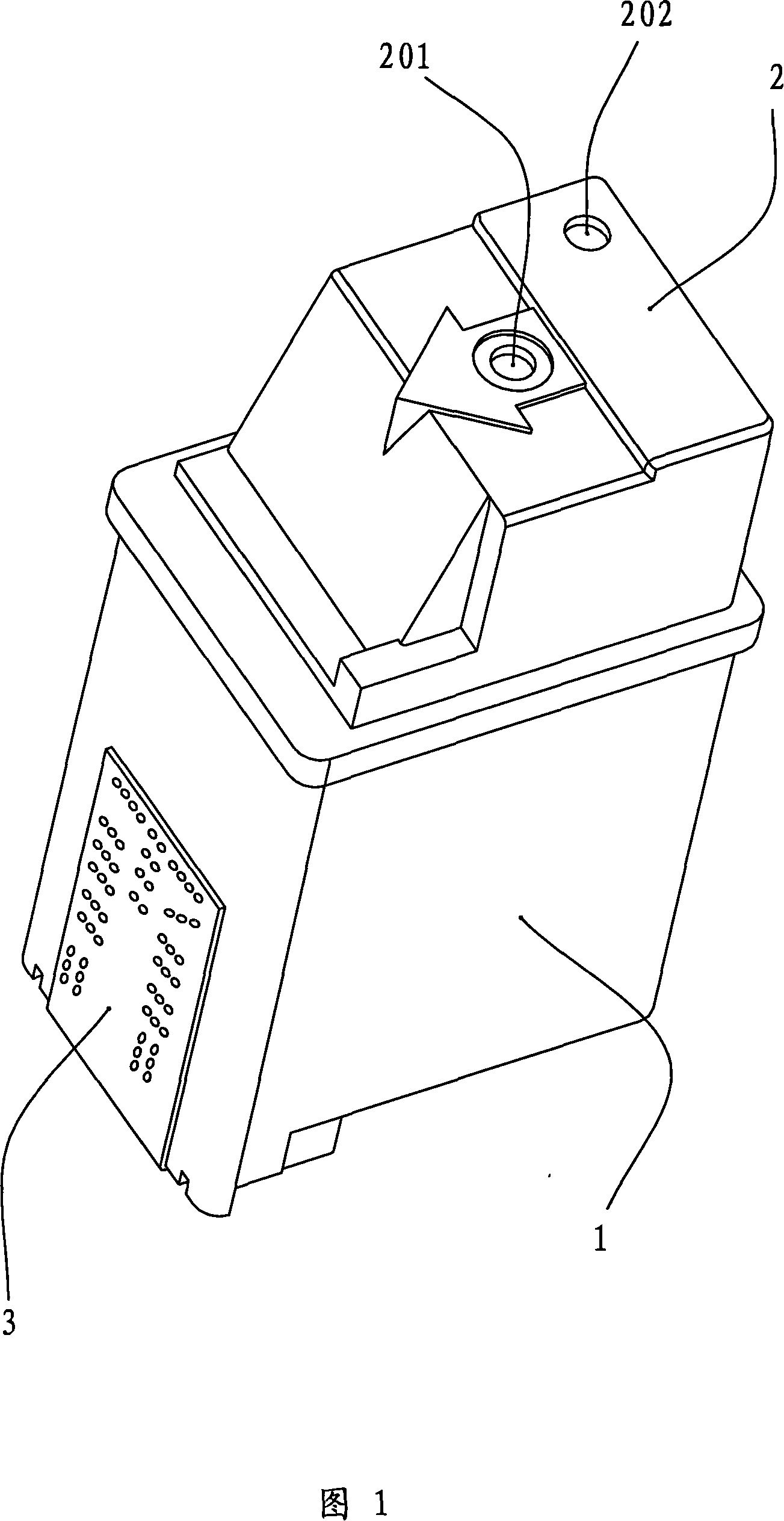
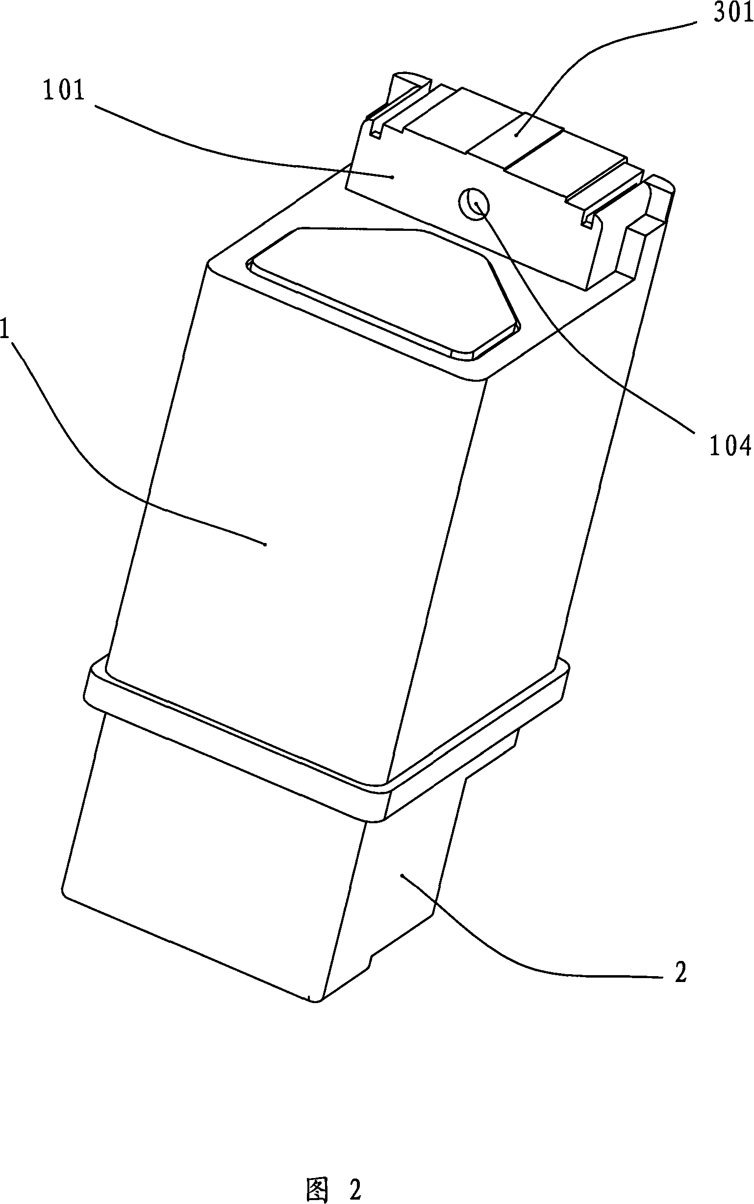
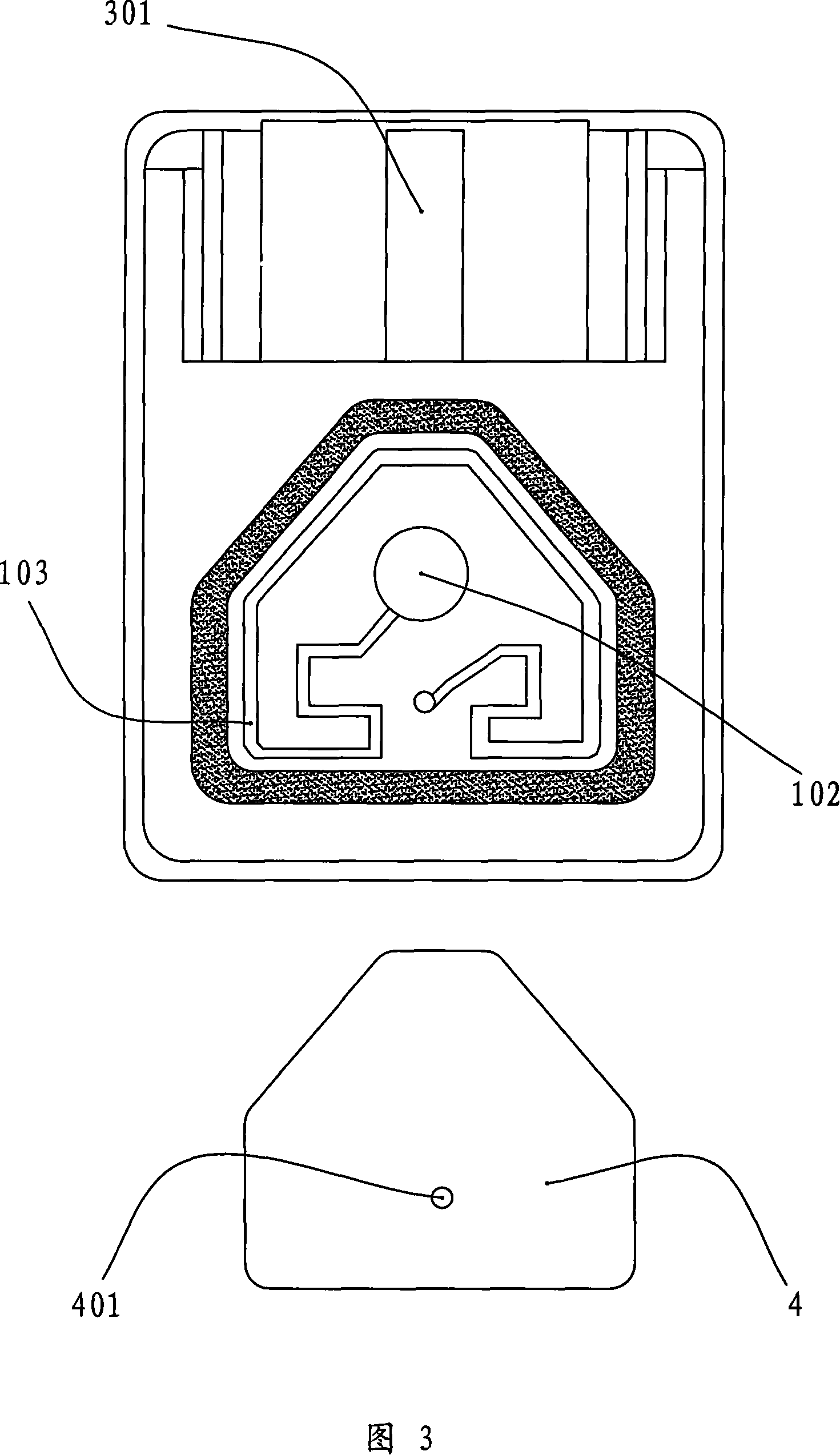
[0033]Referring to Figures 1, 2, and 3, it is a conventional ink jet printer ink cartridge. The shape of the ink cartridge is generally a rectangular parallelepiped, which is formed by connecting and surrounding a plurality of side walls. Its structure includes a box body 1 , a box cover 2 and a print head substrate 3 . After the box body 1 and the box cover 2 are fastened together, a hollow inner cavity of the ink cartridge for storing ink (not shown in the figure) is formed. A boss 101 extends from the bottom end of the box body 1 relative to the box cover 2 . An ink supply port communicated with the ink storage chamber of the ink cartridge is opened on the boss 101 , and the ink supply port is closed by the corresponding print head 301 on the print head substrate 3 . Inside the boss 101 is an ink channel (not shown) that communicates with the ink storage chamber of the ink cartridge and the print head 301 , and constitutes an ink supply passage from the ink storage chambe...

Embodiment 2

[0045] For the ink cartridges with the structures shown in Figures 1, 2, and 3, after the ink in the ink storage chamber is exhausted due to normal use, for example, the ink is normally supplied to the inkjet printer, a recycling method including the following sequential process steps is used to recover the ink regeneration:

[0046] First, an adhesive is applied on the periphery of the air hole 201 of the ink cartridge box cover and the periphery of the adhesive film 4 covering the air hole 102 at the bottom of the box body respectively. UV light irradiates the adhesive to cure it. The wavelength of ultraviolet light is 0.04-0.39 microns, and the irradiation time is 4-8 seconds.

[0047] Next, a first through hole 202 connecting the ink storage chamber and the external atmosphere is formed on the ink cartridge cover 2 by drilling or punching, and a second through hole 202 is formed on the ink cartridge case body wall between the filter screen and the print head 301 Through ...

Embodiment 3

[0054] For the ink cartridges with the structures shown in Figures 1, 2, and 3, after the ink in the ink storage chamber is exhausted due to normal use, for example, the ink is normally supplied to the inkjet printer, a recycling method including the following sequential process steps is used to recover the ink regeneration:

[0055] First, an adhesive is applied around the air hole 201 of the cartridge cover. UV light irradiates the adhesive to cure it. The wavelength of ultraviolet light is 0.04-0.39 microns, and the irradiation time is 4-8 seconds.

[0056] Then, the adhesive film 4 covering the air hole 102 at the bottom of the box is removed and replaced with a new adhesive film. The new adhesive film is fixed on the periphery of the air hole 102 at the bottom of the box body by melting the periphery of the air hole 102 at the bottom of the box body.

[0057] Afterwards, an adhesive with the same composition as that applied to the periphery of the air hole 201 of the c...


PUM


Abstract

The present invention provides a regeneration method of an ink jet printer ink box, which aims at a waste ink box which takes a spring and an airbag as a subpressure regulator structure. A splicing does is smeared around a cover of the ink box and then is solidified by illuminating; or the splicing does is smeared around the air holes at the bottom of the ink box and is plastered with the relative film and then solidified by illuminating. A pylome is opened on the box cover and the box body through which the cleaning liquid is injected and an ink storage and an ink supply road are cleaned in the way. So that the closure performance of the air holes of the regenerated ink box cover and the closing film are improved; the damage to the subpressure regulator structure is avoided; the original subpressure regulator structure is effectively used and the using cost of the ink box is reduced. The passing rate of the recycling ink box products is over 65 percent.

Description

technical field [0001] The invention relates to a method for regenerating ink cartridges of inkjet printers, in particular to a method for regenerating waste ink cartridges of inkjet printers in which a print head and an ink container are integrally arranged, and an air bag and a spring device are arranged in the interior as a negative pressure regulating mechanism. Background technique [0002] Inkjet printers, the printing method is usually to provide ink supply from an ink container, transport ink to the print head through the corresponding ink flow channel, and eject the ink from the nozzle of the print head to the recording medium such as paper under the drive of the printing signal. Complete the recording of characters or graphics. Common commercially available inkjet printers include piezoelectric inkjet printers and thermal bubble inkjet printers. [0003] Piezoelectric inkjet printers are provided with a piezoelectric crystal on the upper and lower sides of the pri...

Claims


Application Information

Patent Timeline
IPC IPC(8): B41J2/175B08B3/08B08B9/00
Inventor 雷海燕
Owner PRINT RITE UNICORN IMAGE PROD CO LTD OF ZHUHAI
Why Eureka
Try Eureka