Turbine shroud segment feather seal located in radial shroud legs

a technology of turbine shroud and feather seal, which is applied in the direction of propellers, propulsive elements, water-acting propulsive elements, etc., can solve the problems of adversely affecting the durability of shroud segments

Active Publication Date: 2008-05-20
PRATT & WHITNEY CANADA CORP
View PDF15 Cites 30 Cited by
  • Summary
  • Abstract
  • Description
  • Claims
  • Application Information

AI Technical Summary

Benefits of technology

[0006]Another aspect of the present invention provides a cooling arrangement in a turbine shroud assembly of a gas turbine engine in which the turbine shroud assembly has a plurality of shroud segments, and in which the shroud segments include platforms disposed circumferentially adjacent one to another collectively to form a shroud ring. Front and rear legs extend radially from an outer surface of the platforms, thereby defining a cavity therebetween. The cooling arrangement comprises a first means for substantially preventing cooling air within the cavity from leakage between the front legs and between the rear legs of adjacent shroud segments and a second means for permitting use of cooling air within the cavity to cool edges between an inner surface and respective opposite sides of the platforms of the respective shroud segments.
[0007]A further aspect of the present invention provides a method for cooling shroud segments of a turbine shroud assembly of a gas turbine engine, comprising steps of (a) continuously introducing cooling air into a cavity defined radially between radial front legs and radial rear legs of the shroud segments and axially between platforms of the shroud segments and an annular support structure; (b) substantially preventing air leakage between the radial front legs and between the radial rear legs of the shroud segments for maintaining a predetermined pressure of the cooling air within the cavity; and (c) continuously directing the cooling air from the cavity through radial passages between platforms of adjacent shroud segments into a gas path defined by the platforms of the shroud segments, thereby cooling sides of the respective shroud segments.

Problems solved by technology

Nevertheless, in conventional cooling arrangements in turbine shroud assemblies, according to thermal analysis, relatively hot spots can occur, for example on opposite side edges of the segment platform, which adversely affect shroud segment durability.

Method used


Image

  • Turbine shroud segment feather seal located in radial shroud legs
  • Turbine shroud segment feather seal located in radial shroud legs
  • Turbine shroud segment feather seal located in radial shroud legs

Examples


Embodiment Construction

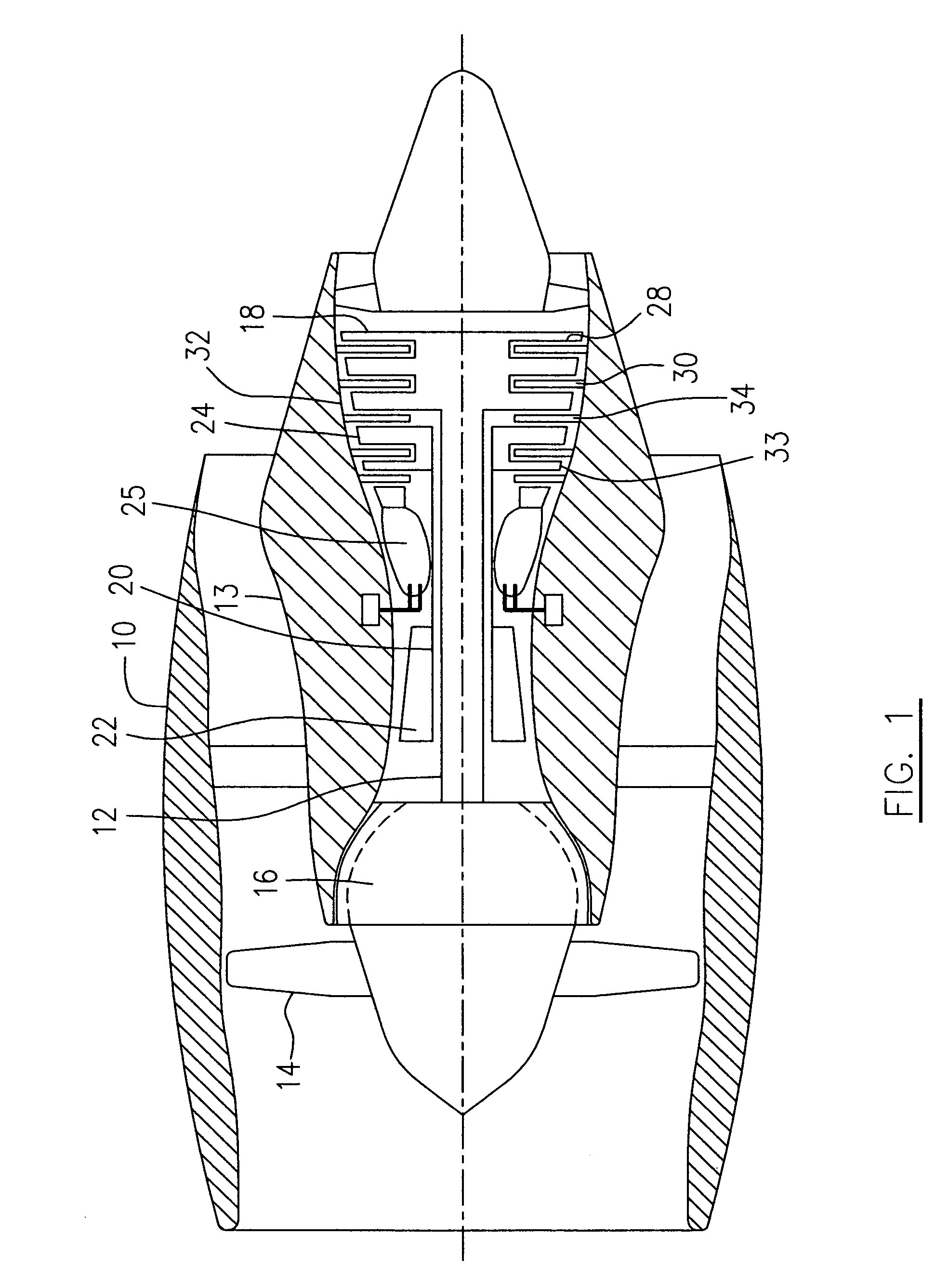
[0014]Referring to FIG. 1, a turbofan gas turbine engine incorporates an embodiment of the present invention, presented as an example of the application of the present invention, and includes a housing or a nacelle 10, a core casing 13, a low pressure spool assembly seen generally at 12 which includes a fan 14, low pressure compressor 16 and low pressure turbine 18, and a high pressure spool assembly seen generally at 20 which includes a high pressure compressor 22 and a high pressure turbine 24. There is provided a burner 25 for generating combustion gases. The low pressure turbine 18 and high pressure turbine 24 include a plurality of rotor stages 28 and stator vane stages 30.

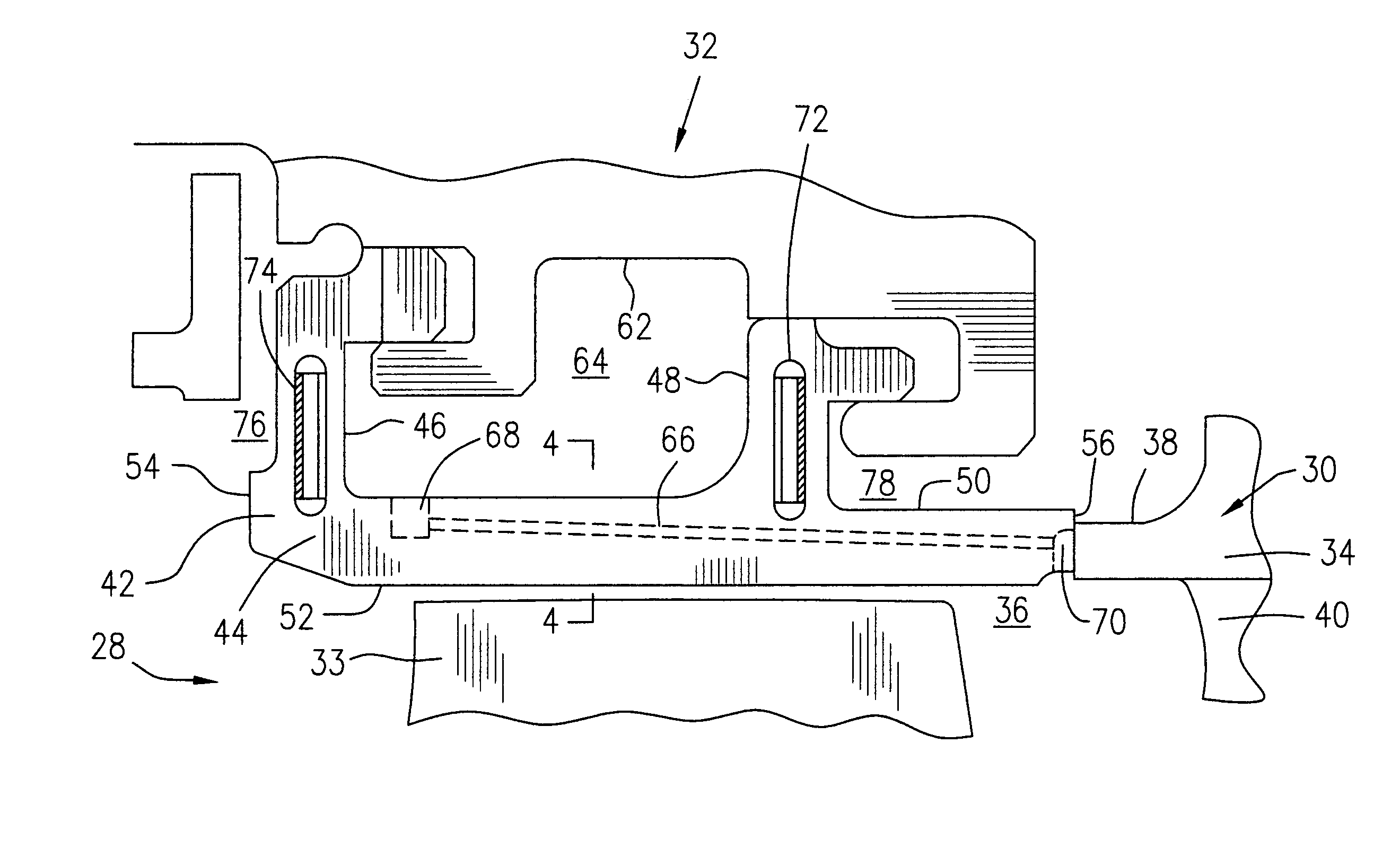
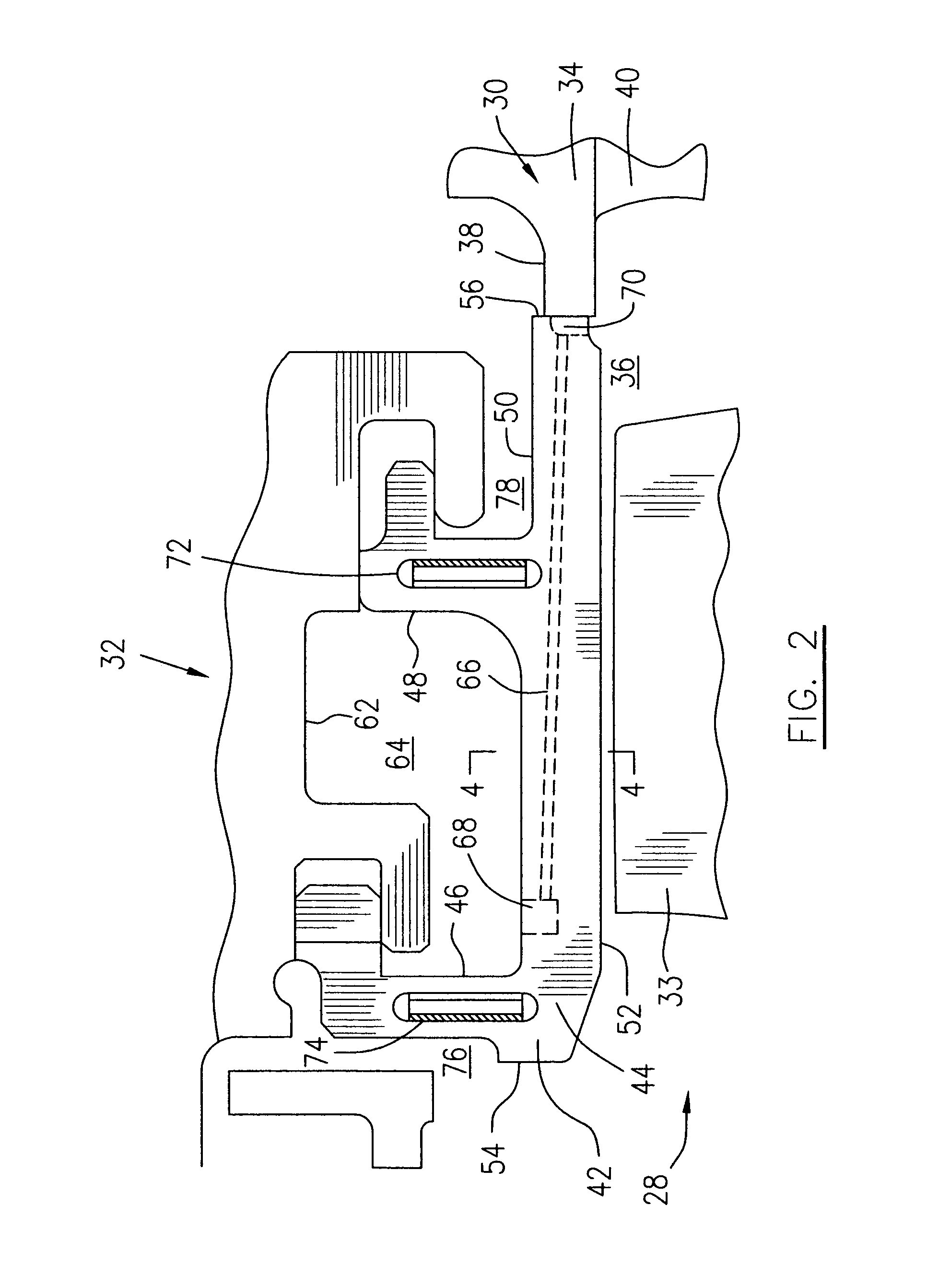
[0015]Referring to FIGS. 1-4, each of the rotor stages 28 has a plurality of rotor blades 33 encircled by a turbine shroud assembly 32 and each of the stator vane stages 30 includes a stator vane assembly 34 which is positioned upstream and / or downstream of a rotor stage 31, for directing combustion gases int...


PUM


Abstract

A turbine shroud assembly is configured to adequately adjust a distribution of cooling air flow such that air leakage between radial shroud legs of adjacent shroud segments is minimized, while permitting cooling air to leak between platforms of adjacent shroud segments in order to cool sides of the platforms thereof.

Description

TECHNICAL FIELD[0001]The present invention relates generally to gas turbine engines and more particularly to turbine shroud cooling.BACKGROUND OF THE ART[0002]A gas turbine shroud assembly usually includes a plurality of shroud segments disposed circumferentially one adjacent to another, to form a shroud ring circling a turbine rotor. Being exposed to very hot gasses, the turbine shroud assembly usually needs to be cooled. Since flowing coolant through the shroud diminishes overall engine performance, it is typically desirable to minimize cooling flow consumption without degrading shroud segment durability. Heretofore, efforts have been made to prevent undesirable cooling flow leakage and to provide adequate distribution of cooling flow to segment parts having elevated temperatures such as the platforms of the shroud segments. Nevertheless, in conventional cooling arrangements in turbine shroud assemblies, according to thermal analysis, relatively hot spots can occur, for example on...

Claims


Application Information

Patent Timeline
Patent Type & Authority Patents(United States)
IPC IPC(8): F04D29/38
CPCF01D9/04F01D11/005F01D11/08F01D25/12F05D2240/11F05D2240/57F05D2260/205F05D2260/203
Inventor DUROCHER, ERICCLERMONT, MARTIN
Owner PRATT & WHITNEY CANADA CORP
Why Eureka
Try Eureka