Structure for cooling a lamp for a projection display apparatus having an integrated exhaust duct

a technology for projection display apparatus and structure, which is applied in the field of structure for cooling a lamp, can solve the problems of incomparable size of lamps, incomparable heat generated by lamps, and inability to cool air, and achieve the effect of preventing the remaining cooling air from remaining and easy removal of lamps

Active Publication Date: 2007-05-24
SHARP NEC DISPLAY SOLUTIONS LTD
View PDF10 Cites 8 Cited by
  • Summary
  • Abstract
  • Description
  • Claims
  • Application Information

AI Technical Summary

Benefits of technology

[0015] It is an object of the present invention to provide a structure for cooling a lamp used for a projection display apparatus, which is compact and allows easy removal of a lamp from a lamp house, and which is capable of uniformly cooling each part of the lamp while preventing cooling air from remaining in the lamp house.
[0017] Since the exhaust duct is integrated with the lamp house cover, a large inlet area can be easily ensured for the duct, and a reduction in the size of the structure is also easy.
[0018] By providing two intake ports for cooling air on the lamp house at locations near the anode and cathode, and by independently cooling the anode and the cathode by means of two fans having an adjustable flow rate, cooling air is efficiently supplied.
[0019] By providing a pair of inlet openings that are formed on the exhaust duct which is on the lamp house cover at locations near the anode and the cathode of the lamp, respectively, cooling efficiency is increased because the cooling air is easily exhausted from the exhaust duct without staying stagnant in the lamp house. By providing the openings near the anode and the cathode of the lamp, respectively, the duct itself can be accommodated in the lamp house, contributing to a reduction in size of the projection display apparatus.
[0020] Further, by forming the inlet openings of the duct portions such that the inlet openings have different opening areas, a larger amount of air tends to enter the opening having a larger opening area. Therefore, part of the cooling air that is introduced to the side of the opening having a smaller opening area tends to flow toward the opening having a larger opening area via the bulb of the lamp, leading to an increased efficiency in cooling the bulb.
[0022] Since the exhaust duct for cooling air is integrated with the removable lamp house cover on the inside of the lamp house cover, a large opening area is ensured for the inlet opening of the exhaust duct. Therefore, cooling efficiency, as well as control of air flow rate, can be improved. In addition, a reduction in size of the structure for cooling the lamp can be achieved because the exhaust duct is arranged inside the lamp house.

Problems solved by technology

However, the digital cinema is different from the conventional cinema in that digital data are used for projection, instead of a film, and are projected onto a screen by a projection display apparatus, or by a digital cinema projector.
Therefore, the amount of heat that is generated by a lamp and the size of a lamp, as well as danger, are incomparably larger than that of a front projector, and the entire size and the total weight of the apparatus also incomparably larger than that of a front projector.
The first problem is how safety can be ensured when replacing a xenon lamp.
The second problem is efficiency for cooling a xenon lamp.
And the third problem is the size of a lamp house or the size of a projection display apparatus.
However, an anode, which is located downstream of a double reflector for a bulb, cannot be sufficiently cooled according to this method because the double reflector has a large diameter.
Also, because a xenon lamp needs to be replaced as a whole and because it is mounted in a congested area in the main body of a projection display apparatus, additional effort is required to replace the xenon lamp.
Therefore, it is not recommended that a user replace a xenon lamp by himself, and replacement work is only performed by those who have training and are qualified by a certifying authority.
Thus, there is a limitation for improving cooling efficiency.
Further, since the cooling air is supplied to the cathode and the anode along a direction that is perpendicular to the optical axis of the lamp, a sufficient amount of cooling air cannot be supplied to the bulb, which makes it particularly difficult to efficiently cool the bulb and to properly control the cooling (temperature setting).
Further, care must be taken to ensure safety during replacement of a lamp, because the size of the opening on the side of the lamp house is limited.

Method used


Image

  • Structure for cooling a lamp for a projection display apparatus having an integrated exhaust duct
  • Structure for cooling a lamp for a projection display apparatus having an integrated exhaust duct
  • Structure for cooling a lamp for a projection display apparatus having an integrated exhaust duct

Examples


Embodiment Construction

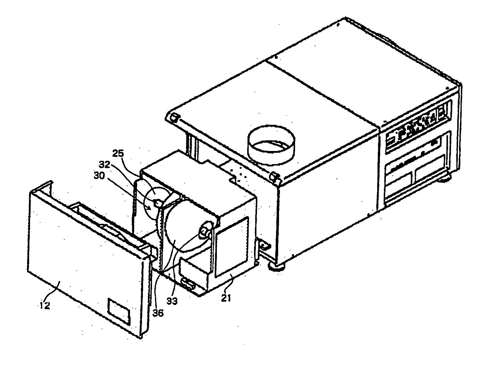
[0035] A projection display apparatus having a structure for cooling a lamp according to an exemplary embodiment of the present invention will be described with reference to the drawings. A xenon lamp is used in the following embodiment because a xenon lamp is preferable as an example for describing the solution of the problems which are mentioned above, i.e., the problem of how safety can be improved when replacing a lamp, the problem of how to efficiently cool a lamp, and the problem of the size of a lamp house or a projection display apparatus itself, as described above. However, the present invention is not limited to a xenon lamp, and can be applied to any light source lamp used for a projection display apparatus, such as a high-pressure mercury lamp, as long as a lamp is provided with an anode and a cathode in front and at the back of a bulb.

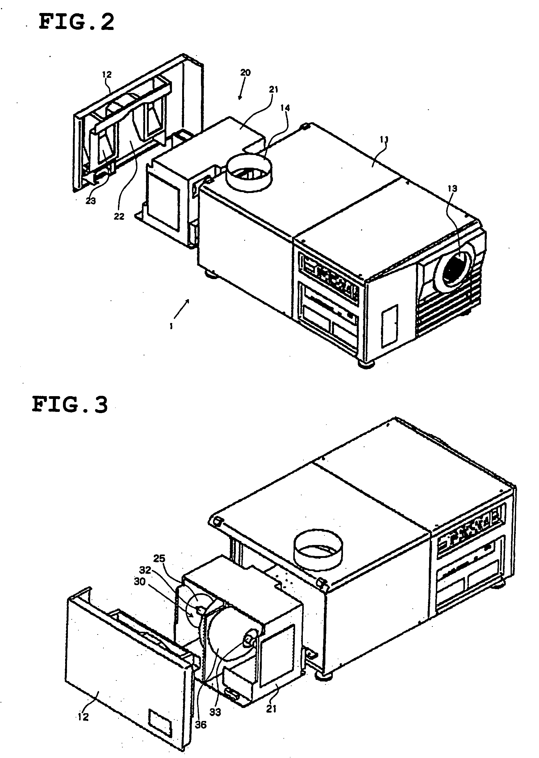
[0036] Referring to FIGS. 2-4, structure 20 for cooling a lamp is provided in housing 11 of projection display apparatus 1. Structure 20...


PUM


Abstract

A structure for cooling a lamp used for a projection type display apparatus is provided. The structure comprises a lamp house for housing a lamp that is operable as a light source, said lamp house being configured to be installed in a housing of said projection display apparatus; and a fan for supplying cooling air into said lamp house. The lamp house comprises a removable lamp house cover, and an exhaust duct for said cooling air is integrated with said lamp house cover.

Description

[0001] The present application is based on, and claims priority from, J.P. Application No. 2005-334148, filed on Nov. 18, 2005, the disclosure of which is hereby incorporated by reference herein in its entirety. BACKGROUND OF THE INVENTION [0002] 1. Field of the Invention [0003] The present invention relates to a structure for cooling a lamp that is used for a projection display apparatus, and more particularly, to a structure for cooling a high-power lamp. [0004] 2. Description of the Related Art [0005] With the reduction in size and improvement in performance of projection display apparatuses, which has been brought about through a rapid advance in liquid crystal technologies and DLP (Digital Light Processing™) technologies, projection display apparatuses for projecting an image have been used in wider fields. The projection display apparatus is drawing attention as a front projector, which is a large projection display apparatus that is replacing conventional home-use television ...

Claims


Application Information

Patent Timeline
Patent Type & Authority Applications(United States)
IPC IPC(8): G03B21/18
CPCG03B21/16G03B21/18
Inventor TAKEDA, MIKIYAKARASUYAMA, GOU
Owner SHARP NEC DISPLAY SOLUTIONS LTD
Why Eureka
Try Eureka