Highly modular loading tools

a tooling and modular technology, applied in the field of loading tooling, can solve the problems of not guaranteeing the uniform treatment of parts, affecting the loading capacity of ovens, and not uniform treatment of parts in a given batch, and achieve the effect of increasing the modularity of loading tooling

Active Publication Date: 2019-05-16
ARIANEGRP SAS
View PDF0 Cites 0 Cited by
  • Summary
  • Abstract
  • Description
  • Claims
  • Application Information

AI Technical Summary

Benefits of technology

[0013]According to a fourth particular characteristic of the loading tooling of the invention, the support arms of each loading stage ar

Problems solved by technology

Although that type of loading tooling enables parts of different shape or sizes to be processed and enables a relatively large filling ratio to be obtained for the oven, it does not guarantee that the parts will be treated uniformly.
Typically, when a gas phase is needed during the heat treatment,

Method used


Image

  • Highly modular loading tools
  • Highly modular loading tools
  • Highly modular loading tools

Examples


Embodiment Construction

[0021]The invention applies in general manner to loading tooling for supporting parts made of metal material during heat treatment or thermochemical treatment of those parts in treatment installations or ovens.

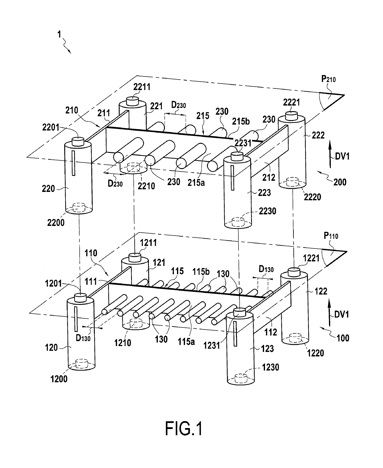
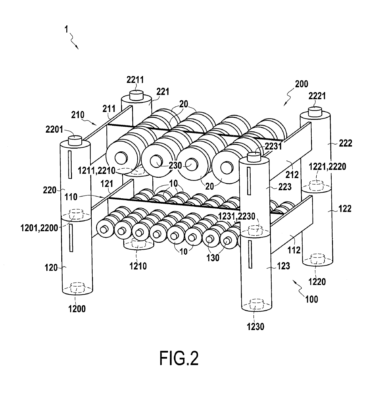
[0022]FIGS. 1 and 2 show loading tooling 1 in accordance with an embodiment of the invention. In this example, the loading tooling 1 comprises a first loading stage 100 and a second loading stage 200 that is designed to be assembled on the first stage 100. The first stage 100 comprises a rack 110 that is supported by four legs 120, 121, 122, and 123. More precisely, the rack 110 comprises a first edge crossbar 111 that connects together the legs 120 and 121 and a second edge crossbar 112 that connects together the legs 122 and 123. A central crossbar 115 extends between the two edge crossbars 111 and 112 and is secured to them. The rack 110 is rectangular in shape. The rack 110 lies in a horizontal plane P110 with the legs 120 to 123 extending in a vertical direction DV1 perpe...


PUM


Abstract

A loading tooling for thermochemical treatment of parts includes at least first and second loading stages stacked one on the other in separable manner, each loading stage including a rack extending in a horizontal plane. The rack is supported by four legs extending in a vertical direction with the legs of the second loading stage standing on the legs of the first loading stage. The rack has a plurality of support arms secured thereto, with the plurality of support arms of the first loading stage presenting an arrangement that is different from the arrangement of the plurality of support arms of the second loading stage.

Description

BACKGROUND OF THE INVENTION[0001]The present invention relates to loading tooling used for supporting parts made of metal materials during heat treatment or thermochemical treatment of those parts, such as annealing, diffusion heat treatment, chemical conversion treatment, forming a surface coating, etc.[0002]Parts for heat treatment or for thermochemical treatment can be loaded into an oven “in bulk”, i.e. in baskets in which the parts are jumbled. Although that type of loading tooling enables parts of different shape or sizes to be processed and enables a relatively large filling ratio to be obtained for the oven, it does not guarantee that the parts will be treated uniformly. Typically, when a gas phase is needed during the heat treatment, the gas does not flow in uniform manner relative to each part, which leads to non-uniformity in the treatment of parts in a given batch.[0003]Another solution consists in using loading tooling that presents specific support devices enabling par...

Claims


Application Information

Patent Timeline
IPC IPC(8): C21D9/00F27D5/00B29C70/16
CPCC21D9/0025F27D5/0012F27D5/0056B29C70/16B29K2307/04F27D2005/0081F27D3/02F27D5/0006
Inventor GUICHARD, FREDERICMAUMUS, JEAN-PIERRECHAUFFAILLE, SEBASTIEN
Owner ARIANEGRP SAS
Why Eureka
Try Eureka