Tpms sensor assembly and method therefore

a technology for mounting assemblies and sensors, applied in vehicle tyre testing, vehicles, instruments, etc., can solve the problems of failure to provide a structure that is selective, failure to provide a connection position assurance feature, and failure to allow for simplified replacement or maintenance of sensor units, etc., to prevent accidental air leakage

Inactive Publication Date: 2006-11-09
FORD GLOBAL TECH LLC
View PDF10 Cites 25 Cited by
  • Summary
  • Abstract
  • Description
  • Claims
  • Application Information

AI Technical Summary

Benefits of technology

[0007] Together with the above-mentioned advantages, a structure for selectively attaching to a wheel and capable of releasably receiving a sensor is provided. Other advantages of the present invention include an attachment mechanism or structure that enables attachment of a sensor to the structure. The sensor may have a standard or specifically designed housing. The structure is also designed for attachment within the wheel, or more particularly into the drop well of a wheel. The structure may be universally compatible with a multitude of wheel designs or over a range of wheel sizes that are available i

Problems solved by technology

However, the mounting system fails to allow for simplified replacement or maintenance of sensor units when the tire is un-mounted from the wheel.
However, these systems fail to disclose a structure wherein a sensor may be releasably attached to the structure, thereby allowing for replacement access to the sensor.
Also, the r

Method used


Image

  • Tpms sensor assembly and method therefore
  • Tpms sensor assembly and method therefore
  • Tpms sensor assembly and method therefore

Examples


Embodiment Construction

[0021] Throughout the figures and in the views, common elements are labeled with the same reference number. The common element may also include an additional number indicating that it is a particular type, kind or style of element for the embodiment presented. The reference numbers indicating a particular type, kind or style of element are not intended to be limiting, and are intended to help the reader in understanding the different embodiments presented in this invention. Reference may be made to the various views of the other figures for a fuller understanding when attention is given to a particular figure.

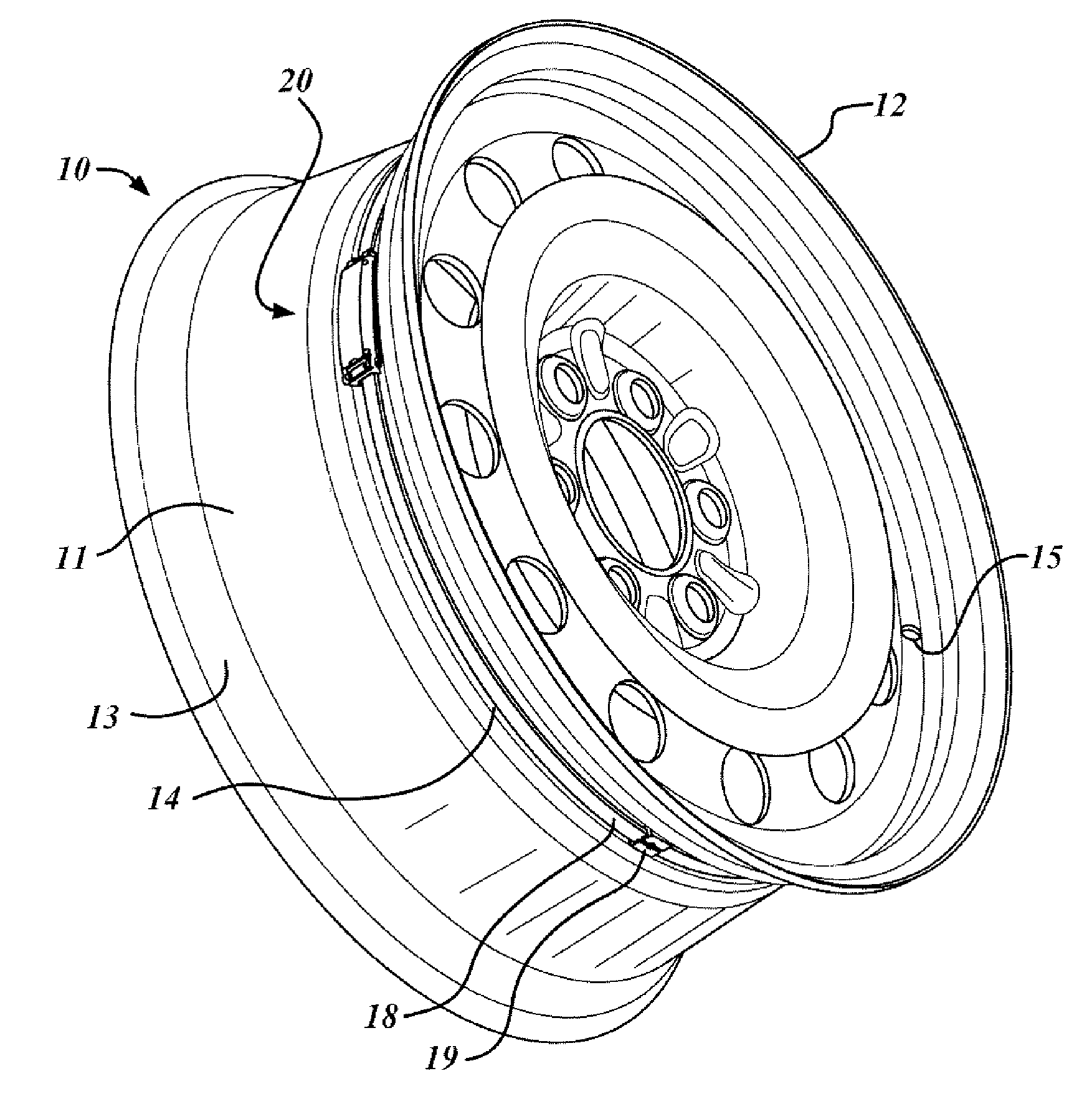
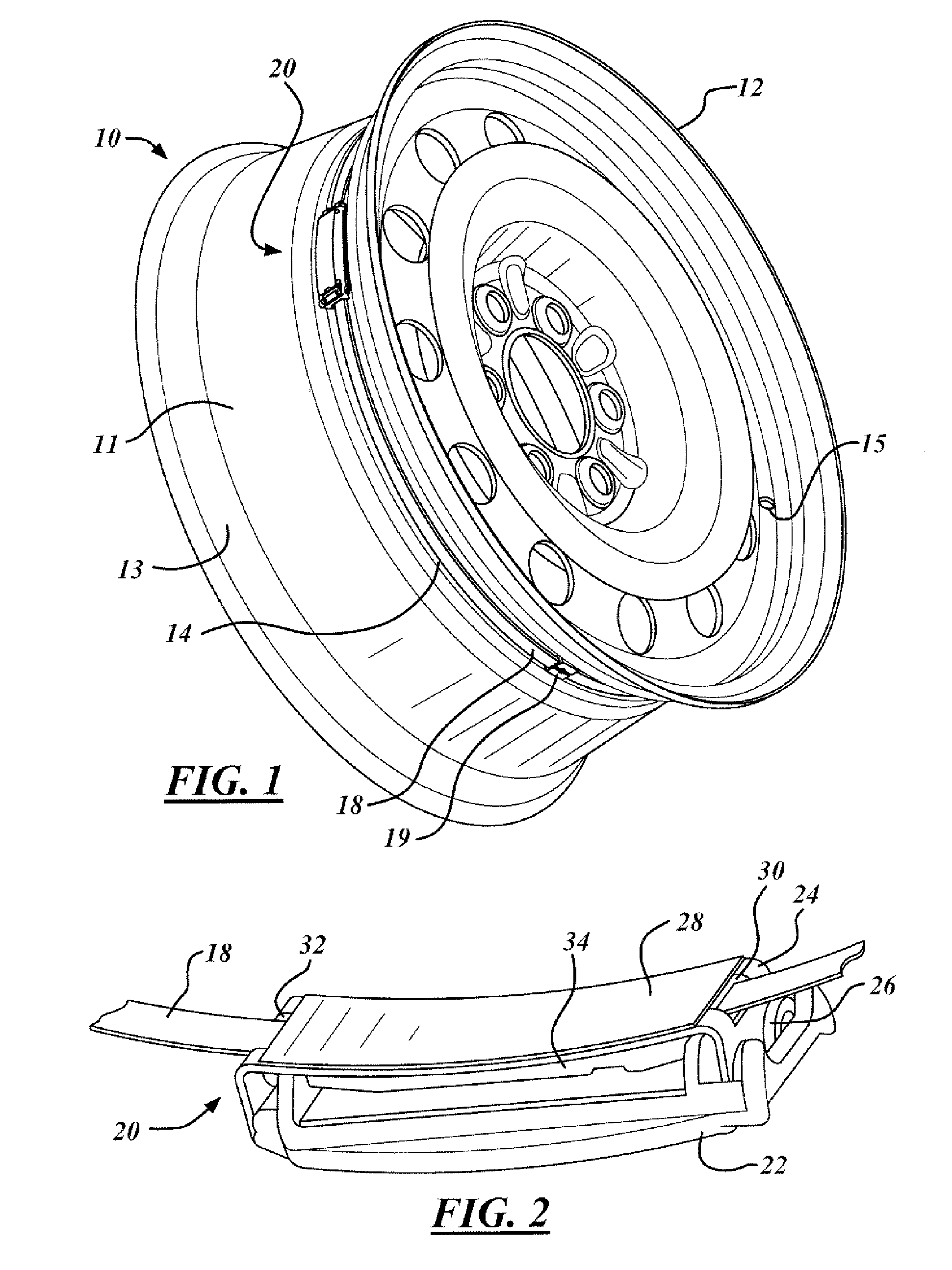
[0022]FIG. 1 shows a perspective view of a TPMS sensor assembly20 being used to advantage on a wheel 10 for an automotive vehicle. The wheel 10 may selectively receive a tire (not shown) for use in an automotive vehicle (not shown). The wheel 10 typically includes a wheel rim 11 having outside rim flange 12 and inside rim flange 13 for sealingly receiving a tire. The wheel 10 ...


PUM


Abstract

A device for removably attaching a TPMS sensor to a wheel is provided. The device has a structure having a first end section, a second end section and a base. The base separates the first end section from the second end section. A first connector is formed in the first end section and a second connector is formed in the second end section. The device may be selectively attached to a wheel. The device may selectively receive a sensor, the sensor being releasably connectable to the first connector and the second connector of the device. The device may be a cradle for connecting a sensor thereto. Also, a method of using a cradle in a first wheel for use with an automotive vehicle is provided.

Description

TECHNICAL FIELD [0001] The present invention generally relates to a sensor mounting assembly for automotive vehicles and, more particularly, to a structure for mounting a sensor to a wheel and a method therefore. BACKGROUND OF THE INVENTION [0002] Various types of pressure sensing systems for monitoring the pressure within the tires of an automotive vehicle have been proposed. Such systems generate a pressure signal using an electromagnetic (EM) signal, which is transmitted to a receiver. The pressure signal corresponds to the pressure within the tire. When the tire pressure drops below a predetermined pressure, an indicator is used to signal the vehicle operator of the low pressure. These systems are becoming known as Tire Pressure Monitoring Systems (TPMS). [0003] Various tire manufacturers have suggested various locations for the pressure sensors. Known systems include coupling a pressure sensor to the valve stem of the tire. Other known systems and proposed systems locate the pr...

Claims


Application Information

Patent Timeline
IPC IPC(8): G01M17/02
CPCB60C23/0498B60C23/0408B60C23/04985B60C23/04G01L17/00
Inventor PHALAK, VINODVERES, ROBERT E.DOUGHERTY, DANIEL P.CROSS, ROBERT L.
Owner FORD GLOBAL TECH LLC
Why Eureka
Try Eureka