
Hydraulic valve and raw material conveying device and method for organic solid waste pyrolysis

A technology of raw material conveying and organic solid waste, applied in the direction of valve operation/release device, valve device, valve details, etc., can solve the problems of easy deformation of hydraulic valve plate, hydraulic valve blockage, etc., to ensure air tightness and high efficiency Conveying and avoiding the effect of amplifying and deforming easily

Pending Publication Date: 2022-07-15
SHANGHAI ELECTRICGROUP CORP
View PDF0 Cites 0 Cited by
  • Summary
  • Abstract
  • Description
  • Claims
  • Application Information

AI Technical Summary

Problems solved by technology

[0005] The technical problem to be solved by the present invention is to overcome the defects of the prior art in the raw material transportation of the organic solid waste pyrolysis system, which cannot solve the problems of air tightness, hydraulic valve blockage, hydraulic valve plate enlargement and easy deformation, etc., and provides A hydraulic valve, raw material delivery device and method for pyrolysis of organic solid waste

Method used


Image

  • Hydraulic valve and raw material conveying device and method for organic solid waste pyrolysis
  • Hydraulic valve and raw material conveying device and method for organic solid waste pyrolysis
  • Hydraulic valve and raw material conveying device and method for organic solid waste pyrolysis

Examples


Embodiment 1

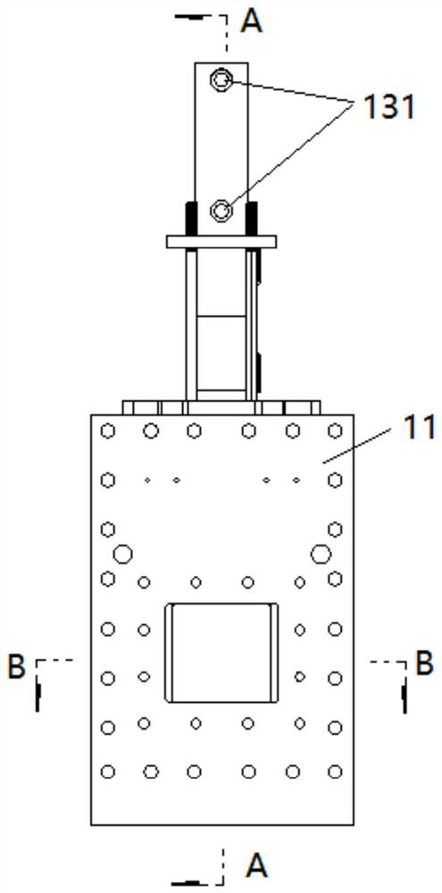
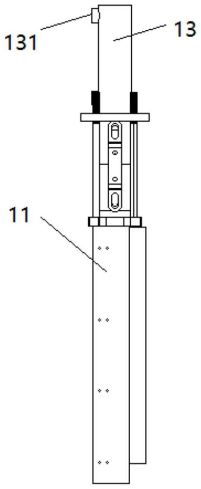
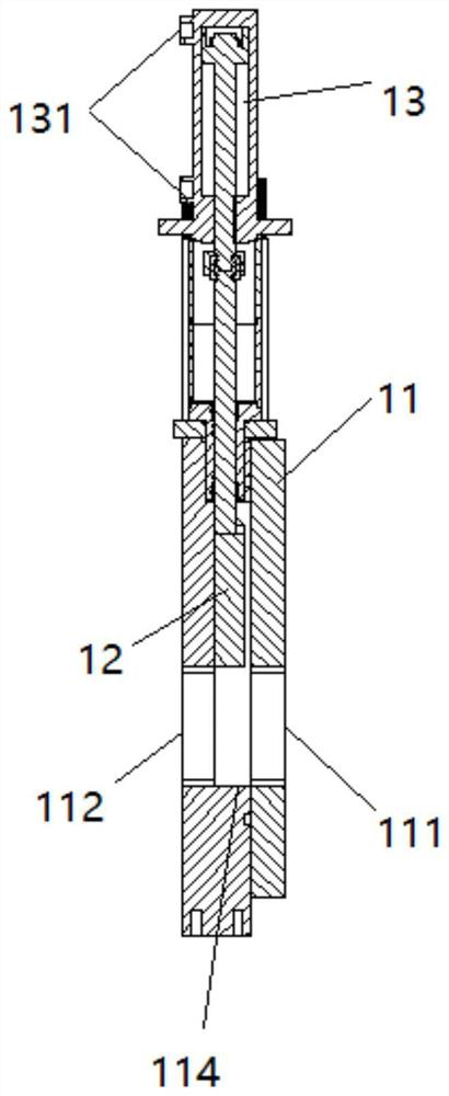
[0062] This embodiment provides a hydraulic valve, refer to Figure 1-5, the hydraulic valve includes: a valve body 11 , a valve plate 12 and a hydraulic cylinder 13 , the valve body 11 includes a feed port 111 and a discharge port 112 , and the hydraulic cylinder 13 includes an oil supply and return port 131 . image 3 for figure 1 Left side sectional view in the direction of middle A, Figure 4 for figure 1 The horizontal section in the direction B in the middle.

[0063] The discharge port 112 is larger than the feed port 111. The valve plate 12 is arranged in the valve body 11 and is located between the feed port 111 and the discharge port 112. The surface of the valve plate 12 relative to the discharge port 112 is larger than that of the valve plate 12 relative to the discharge port 112. The surface of the feed port 111.

[0064] The valve plate 12 is used to control the communication area between the inlet port 111 and the outlet port 112 under the action of hydrauli...

Embodiment 2

[0077] This embodiment provides a raw material conveying device for pyrolysis of organic solid waste. refer to Image 6 , The raw material conveying device includes: hydraulic valve 1, first hydraulic press 2, push material pipeline 3, push material piston, feed bin 5, platen valve 6, first sealed pipe 7, second sealed pipe 8 and second hydraulic press.

[0078] The hydraulic valve 1 is the hydraulic valve in the first embodiment.

[0079] The first hydraulic press 2 is fixedly connected with the first end of the pushing pipe 3 , the hydraulic rod of the first hydraulic press 2 is fixedly connected with the pushing piston, and the pushing piston is located in the pushing pipe 3 .

[0080] The second end of the push pipe 3 is communicated with the push port of the feed bin 5, the discharge port of the feed bin 5 is communicated with the first end of the first sealing pipe 7, and the second end of the first sealing pipe 7 is communicated with the hydraulic valve The feed port ...

Embodiment 3

[0112] This embodiment provides a raw material conveying method for pyrolysis of organic solid waste. The raw material conveying method is realized by using the raw material conveying device for pyrolysis of organic solid waste in Example 2.

[0113] refer to Figure 8 , the raw material conveying method includes:

[0114] S11. Control the platen valve to compress the raw materials in the feed bin.

[0115] S12, controlling the pushing piston to push the compressed raw material into the first sealing pipe.

[0116] S13. When the pressure value of the first hydraulic press reaches the pressure threshold, control the hydraulic valve to be in an open state, so that the raw material enters the second sealed pipeline from the first sealed pipeline.

[0117]Among them, the raw material continues to enter the first sealed pipeline under the push of the pushing piston, which increases the pressure value of the first hydraulic press. The pressure value of the first hydraulic press ...


PUM


Abstract

The invention provides a hydraulic valve and a raw material conveying device and method for organic solid waste pyrolysis. The hydraulic valve comprises a valve body and a valve plate. The valve body comprises a feed port and a discharge port; the discharging port is larger than the feeding port, the valve plate is arranged in the valve body and located between the feeding port and the discharging port, and the surface, opposite to the discharging port, of the valve plate is larger than the surface, opposite to the feeding port, of the valve plate. The valve plate is used for controlling the communication area between the feeding port and the discharging port under the hydraulic action. According to the hydraulic valve, unique design is adopted, it is ensured that fabric filamentous garbage in raw materials cannot block the movement of the valve body, and the situation that a hydraulic valve plate is enlarged and prone to deformation is avoided. According to the raw material conveying device, material blockage of the hydraulic valve is avoided, the situation that a hydraulic valve plate is enlarged and prone to deformation is avoided, air tightness is achieved, efficient conveying of raw materials of the organic solid waste pyrolysis system is achieved, and operation and maintenance are easy.

Description

technical field [0001] The invention relates to the technical field of garbage disposal, in particular to a hydraulic valve, a raw material conveying device and method for pyrolysis of organic solid waste garbage. Background technique [0002] The organic solid waste pyrolysis process aims at high-value utilization of solid waste. Based on the thermal decoupling coupled gasification technology, the chemical energy of solid waste is converted into gas, which can be used as fuel gas, heating, blending, power generation, etc. To achieve the purpose of effective harmlessness and reduction, at the same time, compared with direct incineration, it has a higher resource utilization capacity, which can greatly improve the flexibility of the project. The pyrolysis process requires control of the amount of oxygen entering the pyrolysis reactor, thus requiring a feed system suitable for the pyrolysis process of organic solid waste. [0003] For the raw material transportation of the or...

Claims


Application Information

Patent Timeline
Patent Type & Authority Applications(China)
IPC IPC(8): F16K3/02F16K3/314F16K31/122F16K3/06
CPCF16K3/02F16K3/314F16K31/122F16K3/0227F16K3/06
Inventor 郭泗勇茹斌曾志伟程文丰
Owner SHANGHAI ELECTRICGROUP CORP
Learn More