Dimmer circuit applicable for LED device and control method thereof

Inactive Publication Date: 2011-12-01
UNITED POWER RES TECH CORP
View PDF7 Cites 172 Cited by
  • Summary
  • Abstract
  • Description
  • Claims
  • Application Information

AI Technical Summary

Benefits of technology

[0024]One object of the invention is to use a frequency modulation control meth

Problems solved by technology

The above-mentioned problems may happen while a TRIAC (t

Method used


Image

  • Dimmer circuit applicable for LED device and control method thereof
  • Dimmer circuit applicable for LED device and control method thereof
  • Dimmer circuit applicable for LED device and control method thereof

Examples


Embodiment Construction

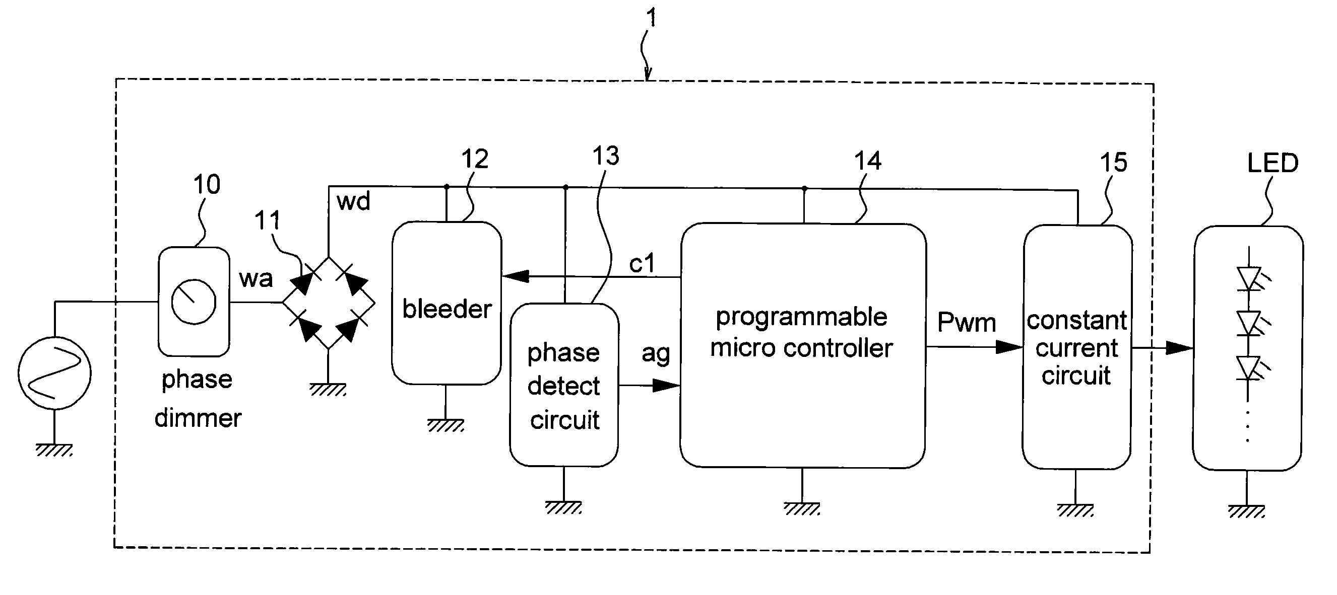
[0036]The following embodiments uses a TRIAC (triode for alternating current) dimmer circuit as examples to illustrate the present invention. It should be noted that the present invention is not limited to the TRIAC. The present invention may applicable to current or future switch elements. Those who are skilled in the art may modify the technique of the present invention which is still within the scope of the present invention.

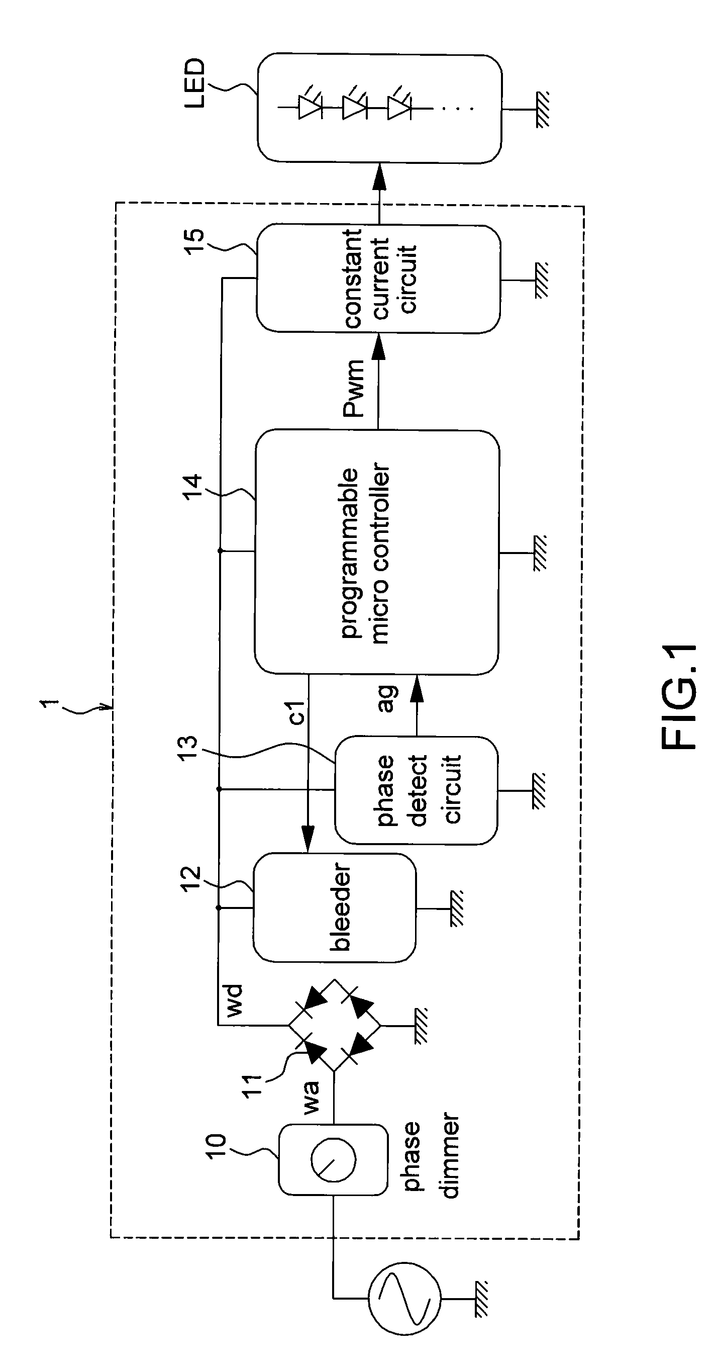
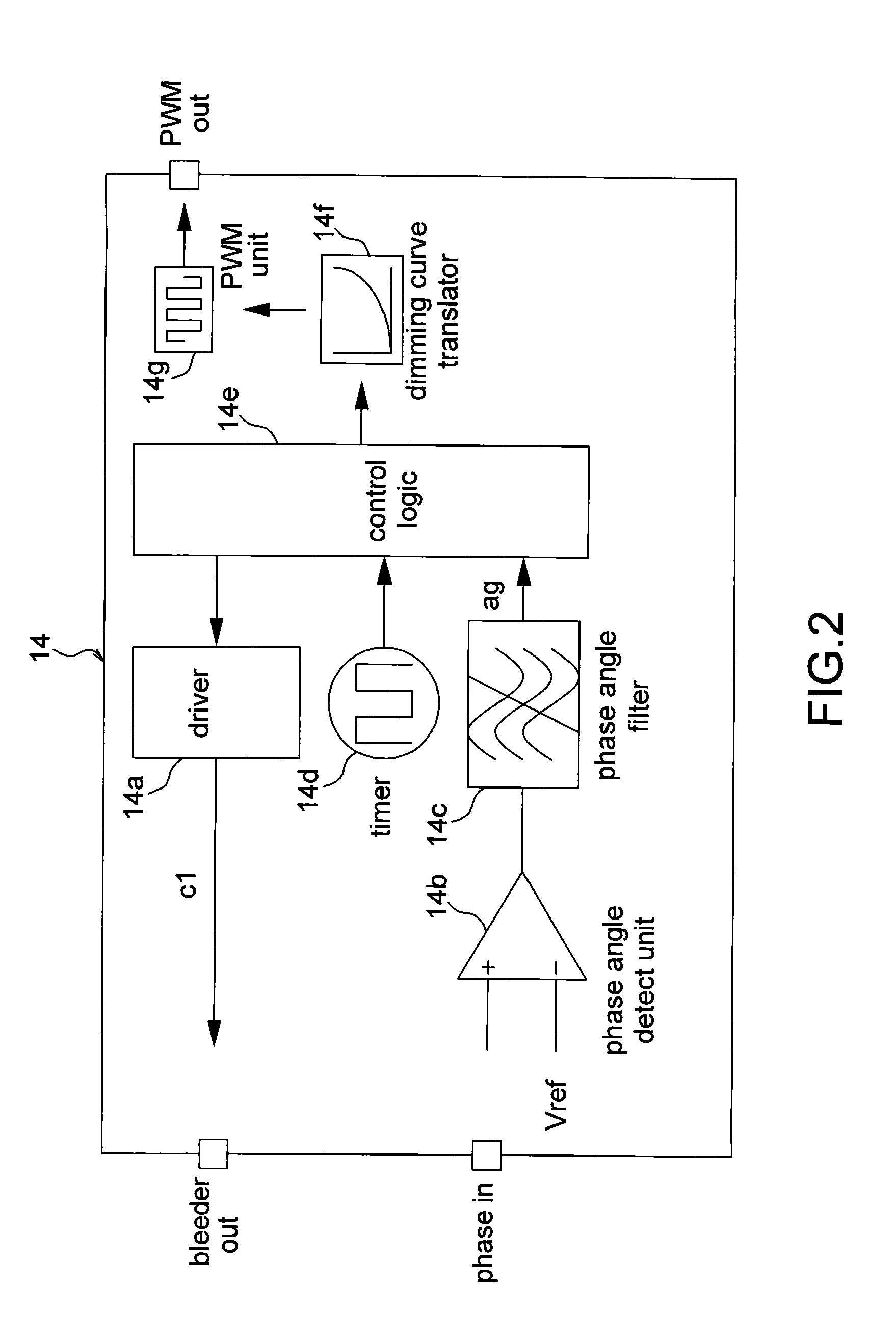
[0037]FIG. 1 is a schematic diagram illustrating an embodiment of a dimmer circuit. The dimmer circuit 1 is applicable to a light emitting diode (LED) device. The dimmer circuit 1 includes a phase dimmer 10, a rectifier 11, a bleeder 12, a phase detect circuit 13, a programmable micro controller 14 and a constant current circuit 15. In an embodiment, the constant current circuit 15 may be optional.

[0038]The phase dimmer 10 generates an AC signal wa corresponding to an adjustment by a user. The rectifier 11 rectifies the AC signal to generate a DC signal wd. T...


PUM


Abstract

A dimmer circuit applicable for LED device and control method thereof is disclosed in the embodiments of the present invention. The dimmer circuit is applicable for controlling at least a LED device. The dimmer circuit includes a rectifier, a bleeder, a phase angle detect circuit, a constant current circuit and a programmable micro controller. The phase angle detect circuit couples to the programmable micro controller. The constant current circuit couples to the LED device The programmable micro controller generates a PWM signal according to the output signal of the phase angle detect circuit to adjust current of the constant current circuit.

Description

BACKGROUND OF THE INVENTION[0001]This application claims the benefit of the filing date of Taiwan Application Ser. No. 099117507, filed on Jun. 1, 2010 and No. 099146213, filed on Dec. 28, 2010, the contents of which are incorporated herein by reference.[0002](a) Field of the Invention[0003]The invention relates to a dimmer circuit and a control method.[0004](b) Description of the Related Art[0005]A conventional TRIAC (Triode for alternating current) dimmer is used to control an incandescent lamp. The TRIAC dimmer outputs an output signal to the incandescent lamp. Further the TRIAC dimmer adjusts phases of the output signal to change the signal output power so as to adjust the luminance of the incandescent lamp. A TRIAC is triggered by a conducting current (latch current Ilatch), and is maintained in a conducting state by a holding current Ihold. Thus a TRIAC should work between the latch current Ilatch and the holding current Ihold for keeping a steady state.[0006]Since a TRIAC wor...

Claims


Application Information

Patent Timeline
IPC IPC(8): H05B41/16
CPCH05B33/0815H05B37/0263H05B33/0845H05B45/10H05B45/37H05B45/31H05B45/325H05B45/3575H05B47/185
Inventor SHEN, FENG-MIN
Owner UNITED POWER RES TECH CORP
Why Eureka
Try Eureka