Male Connector and Transfusion Line Connection Apparatus Equipped With Male Connector

Active Publication Date: 2011-12-15
KPR U S LLC
View PDF3 Cites 42 Cited by
  • Summary
  • Abstract
  • Description
  • Claims
  • Application Information

AI Technical Summary

Benefits of technology

[0013]The transfusion line includes the male connector, as described above, and a female connector. The female connector includes a septum having an insertable connection tube positioned on the outer cylinder body section of the female connector and seal inside of the connection tube where a slit is formed for the reception of the movable blunt needle of the male connector. When the movable blunt needle is inserted into the slit of the female connector the movable blunt needle moves in the axial direction at the posterior end to open the valve of the male connector due to the shoulder contacting the septum. In this way the inlet channel of the movable blunt needle is open and medical fluids can flow through the male and female connectors.
[0014]The movable blunt needle of the male connector is positioned so that the movable blunt needle has a flow path which can be moved in the axial direction relative to the movable blunt needle retainer. The male connector includes a valve which is positioned at the posterior end such that the flow channel inlet of the movable blunt needle is blocked. The valve is opened as a result of the posterior end of the movable blunt needle pressing against the valve when the movable blunt needle is moved in the axial direction. When the movable blunt needle is inserted into the corresponding connector, it moves in the axial direction and opens the valve due to the shoulder being in contact with the corresponding connector. This causes the flow channel inlet of the movable blunt needle to be open thereby allowing medical fluids to fl

Problems solved by technology

However, this protective shutter only retains the injector by the radial constriction flexibility of the injector.
Also, since the protective shutter moves along the axis of the injector with an enlarged diameter when the male and female connectors are attached or de

Method used


Image

  • Male Connector and Transfusion Line Connection Apparatus Equipped With Male Connector
  • Male Connector and Transfusion Line Connection Apparatus Equipped With Male Connector
  • Male Connector and Transfusion Line Connection Apparatus Equipped With Male Connector

Examples


embodiment 1

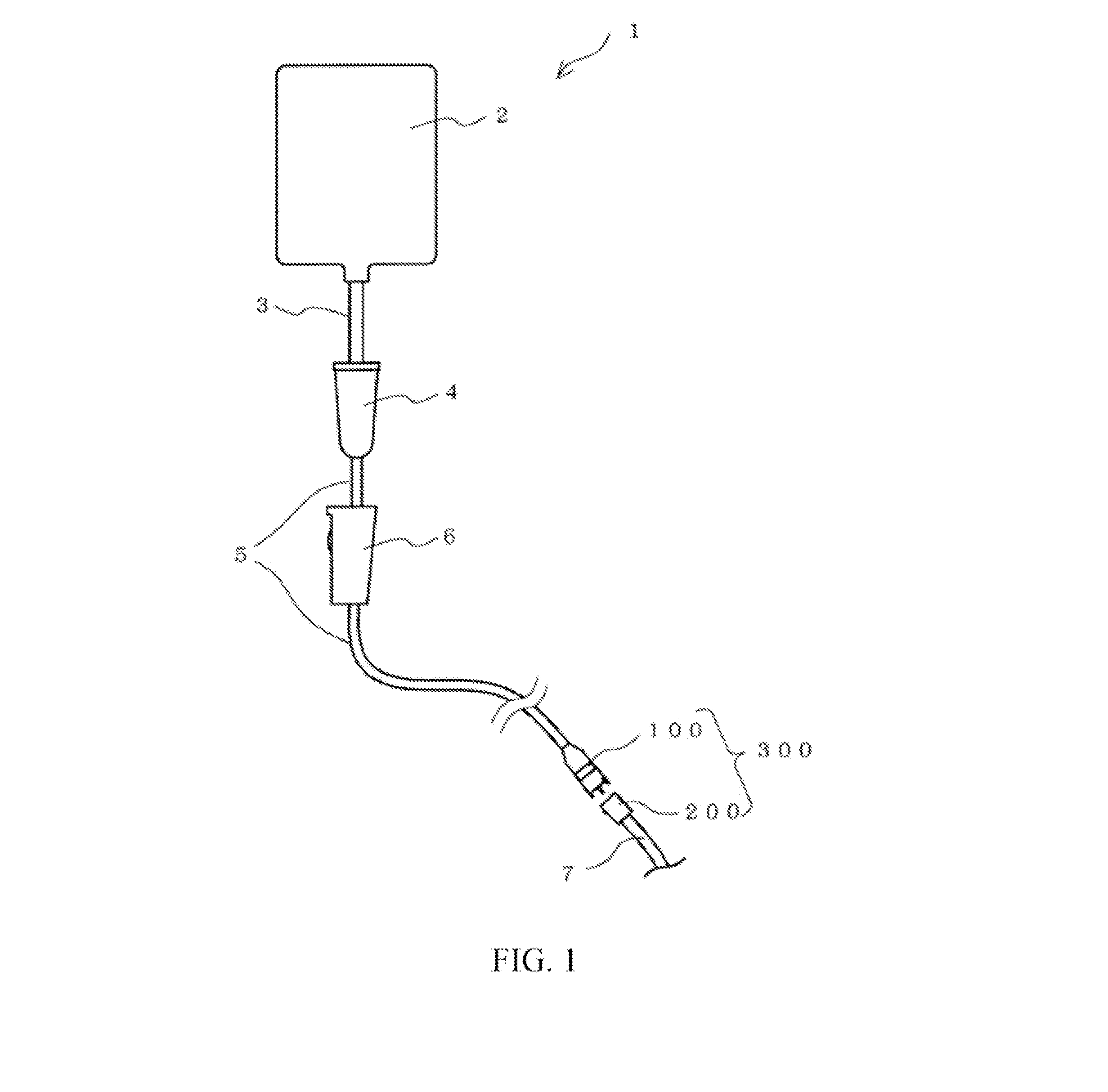
[0028]FIG. 1 shows an example of the structure of the transfusion line set according to embodiment 1. The transfusion line set 1 is adapted to supply medical fluid such as a drug solution, etc., and includes a fluid container 2 which contains the medical fluid, a tube 3, an infusion tube 4, a tube 5, a roller clamp 6, a transfusion line connection apparatus 300 including a male connector 100 and a female connector 200, and a tube 7.

[0029]Fluid container 2 is a container for storing various medical fluids such as drug solutions, nutrients, anti-cancer drugs, saline, and blood. Infusion tube 4 temporarily accumulates the drug solution supplied from liquid container 2 through tube 3 as well as sending a predetermined amount of the medical fluid to roller clamp 6 through tube 5. Roller clamp 6 is adapted for regulating the flow of the medical fluid supplied through tube 5 by compressing soft tube 5. If tube 5 is compressed to the maximum, the flow of medical fluid can be halted.
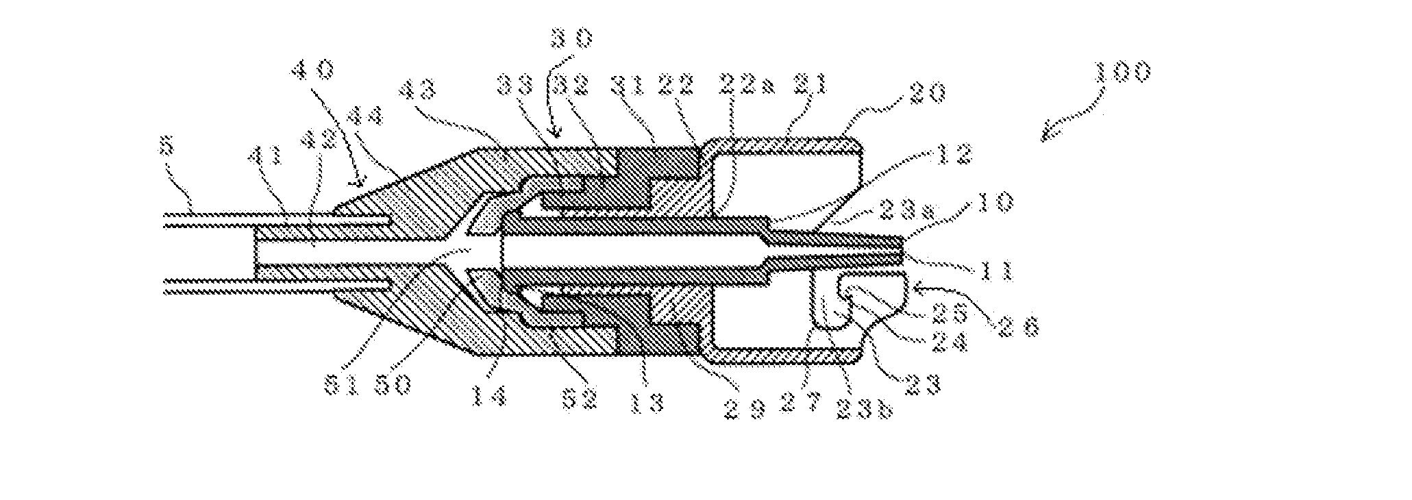
[0030]Ma...

embodiment 2

[0060]In embodiment 2, there is disclosed an example of a movement regulation component which regulates excessive axial movement of movable blunt needle 10A of the male connector 100. Embodiment 2 mainly describes the differences with embodiment 1 and identical or corresponding structure as that of embodiment 1 is given similar symbols.

[0061]FIGS. 6A and 6B are figures that show the connection device of the infusion line of embodiment 2, FIG. 6A shows a cross-sectional schematic view of male connector 100, FIG. 6B shows a cross-sectional schematic of the connection state of male connector 100A and female connector 200. As FIGS. 6A and 6B show, the outer diameter of movable blunt needle 10A has a smaller diameter at a predetermined position in the axial direction at the posterior end relative to shoulder 12 and has a larger diameter as compared with the inner diameter of the blunt needle retainer tube 29 at shoulder 12. The part where the outer diameter is larger than blunt needle re...

embodiment 3

[0064]Embodiment 3 discloses configuration examples other than the movement regulation component established in the movable blunt needle of the male connector. FIG. 7 is a schematic cross-section of male connector 100B according to embodiment 3. Embodiment 3 mainly explains the differences with embodiment 2 and identical or corresponding structure as that of embodiments 1 and 2 is given similar symbols.

[0065]Instead of shoulder 12, movable blunt needle 10B includes a movement regulation component 60B disposed in a predetermined position of axial movement. In embodiment 3, movement regulation component 60B of movable blunt needle 10B is a projection projecting outward circumferentially from movable blunt needle 10B. At least two of the projections (one pair) of movement regulation component 60B are disposed at an opposing position of the circumferential position of movable blunt needle 10B. When valve 50 is in an open state due to the axial movement of movable blunt needle 10B, the m...


PUM


Abstract

The male connector of the present disclosure allows for the flow of fluids and includes a movable blunt needle having a shoulder projecting outwards from the movable blunt needle and extending proximally from the movable blunt needle. The male connector also includes an outer cylinder body formed around the movable blunt needle and disposed in coaxial alignment to the movable blunt needle and a movable blunt needle retainer which retains the movable blunt needle is movable in an axial direction and a valve which opens as a result of the movable blunt needle moving in the axial direction where the posterior end presses against the valve to open the valve. This occurs when the movable blunt needle is inserted at the destination of the connection in a status where the inlet of the flow channel side of the movable blunt needle is open and such that the shoulder presses against the destination of the connection.

Description

BACKGROUND[0001]1. Technical Field[0002]The present disclosure relates to a male connector of a transfusion line which conducts fluids such as drug solutions to patients and transfusion line connection apparatus for use with the connector cap.[0003]2. Background of the Related Art[0004]During conventional medical procedures, medical fluids such as drug solutions and blood, etc. are supplied to a patient by a transfusion system through a tube. Within this type of transfusion system, connection equipment is used to provide throughflow between tubes by including male and female connectors at the end of the tubes.[0005]A transfusion system that can prevent leaks is desirable to prevent fluid from contacting medical staff and patients. This is important because medical fluids that are supplied by the transfusion system, such as anti-cancer and transfusion drugs, may have induced characteristics or may cause side effects such as cytopathy, genotoxicity, carcogenicity, and fetal malformati...

Claims


Application Information

Patent Timeline
IPC IPC(8): A61M39/10
CPCA61M39/1011A61M2039/1027A61M2039/1094A61M2039/1072A61M2039/1033
Inventor MIYASAKA, SUSUMU
Owner KPR U S LLC
Why Eureka
Try Eureka