Display panel and display device

a display panel and display panel technology, applied in the field of display panel and display device, can solve the problem of low light use efficiency and achieve the effects of improving light use efficiency, reducing contrast, and facilitating acquisition

Inactive Publication Date: 2012-01-26
SHARP KK
View PDF1 Cites 43 Cited by
  • Summary
  • Abstract
  • Description
  • Claims
  • Application Information

AI Technical Summary

Benefits of technology

[0049]As described above, according to the present invention, it is possible to easily obtain: a display panel which is able to alleviate the contrast becoming low and improve the light use efficiency; and a display device that includes the display panel.

Problems solved by technology

However, in the conventional display device, in each display region, the color filter blocks the light of two colors of the red light, the green light and the blue light, so that there is a disadvantage that the light use efficiency is low.

Method used


Image

  • Display panel and display device
  • Display panel and display device
  • Display panel and display device

Examples


first embodiment

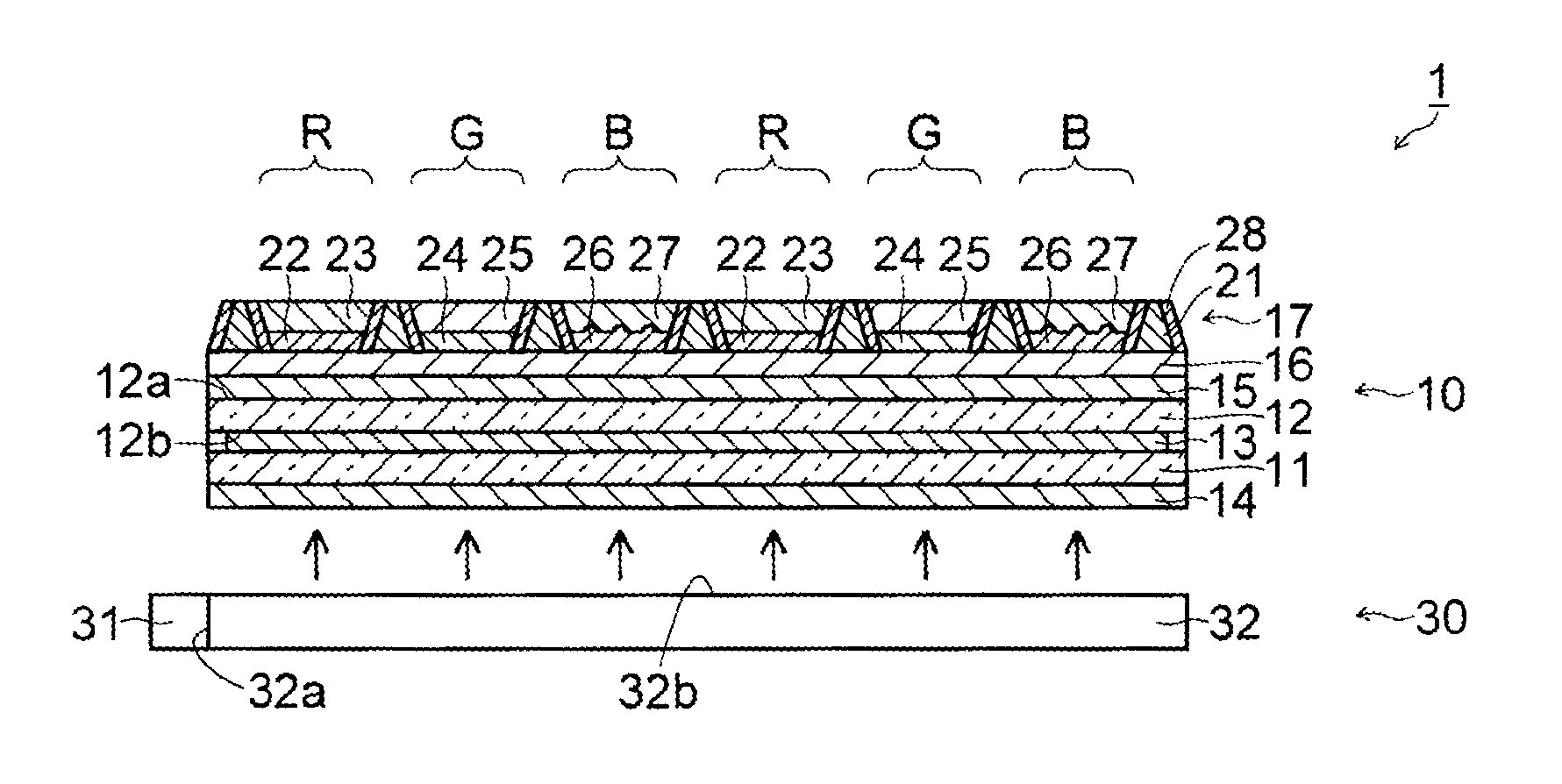
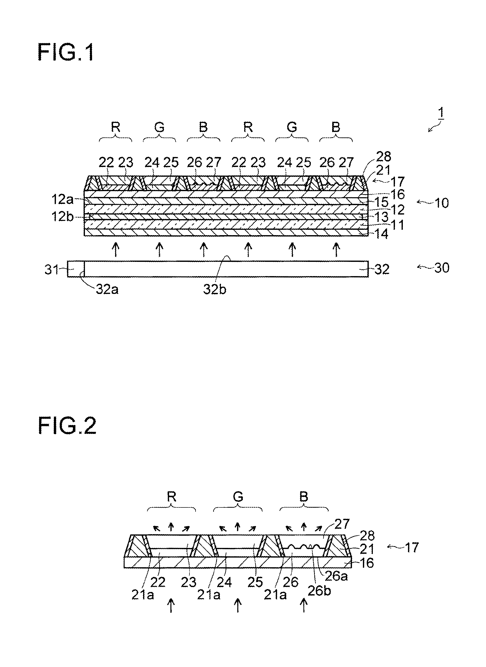
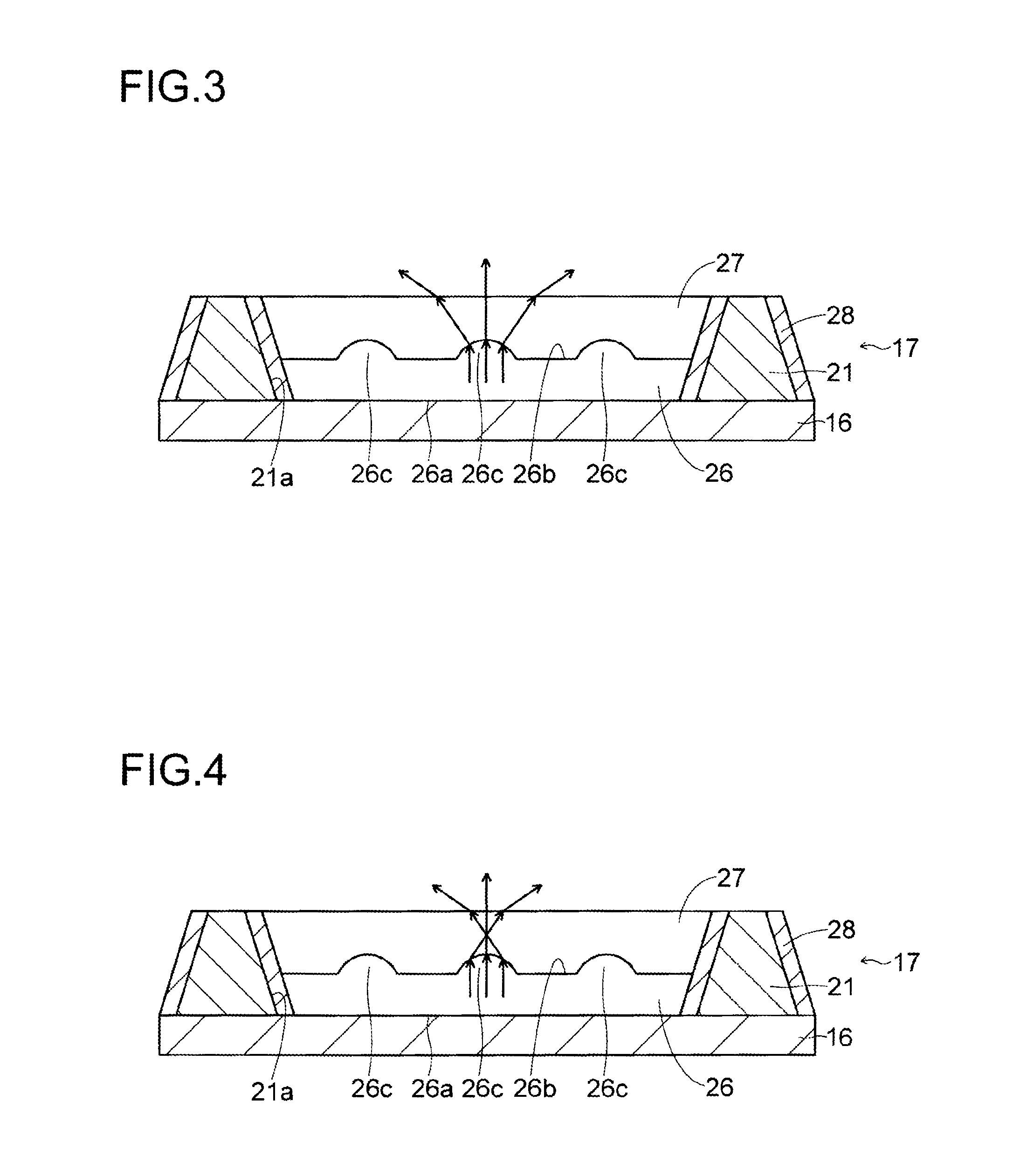
[0063]With reference to FIG. 1 to FIG. 4, a structure of a liquid crystal display device 1, which includes a liquid crystal display panel 10 according to a first embodiment of the present invention, is described.

[0064]The liquid crystal display device 1 according to the first embodiment of the present invention, as shown in FIG. 1, includes: the liquid crystal display panel 10: a backlight device 30 that is disposed to a rear-surface side of the liquid crystal display panel 10 and shines blue light onto the liquid crystal display panel 10; and a frame (not shown) that holds the liquid crystal display panel 10 and the backlight device 30. Here, the liquid crystal display device 1 is an example of a “display device” according the present invention; and the liquid crystal display panel 10 is an example of a “display panel” according to the present invention.

[0065]The liquid crystal display panel 10 includes: an AM board (active matrix board) 11; an opposite board 12 that is disposed op...

second embodiment

[0110]In a second embodiment, with reference to FIG. 5 to FIG. 7, unlike the above first embodiment, a case, where a light output surface 56b of a transparent resin layer 56 is provided with a plurality of concave portions 56c, is described.

[0111]In a color filter 47 of a liquid crystal display panel according to the second embodiment of the present invention, as shown in FIG. 5, in the opening portion 21a of the blue display region B, the transparent resin layer 56 and a blue filter layer 57 are formed. And, the transparent resin layer 56 and the blue filter layer 57 constitute a “blue transmission layer” of the present invention. Here, the transparent resin layer 56 is an example of a “light diffusion layer” of the present invention. Besides, the blue filter layer 57 is an example of a “layer that is in contact with a surface which is provided with least either of a plurality of convex portions and a plurality of concave portions” of the present invention.

[0112]Here, in the second...

third embodiment

[0117]In a third embodiment, with reference to FIG. 8, unlike the above first and second embodiments, a case, where a light output surface 76b of a transparent resin layer 76 is provided with both of a plurality of convex portions 76c and a plurality of concave portions 76d, is described.

[0118]In a color filter 67 of a liquid crystal display panel according to the third embodiment of the present invention, as shown in FIG. 8, in the opening portion 21a of the blue display region B, the transparent resin layer 76 and a blue filter layer 77 are formed. And, the transparent resin layer 76 and the blue filter layer 77 constitute a “blue transmission layer” of the present invention. Here, the transparent layer 76 is an example of a “light diffusion layer” of the present invention. Besides, the blue filter layer 77 is an example of a “layer that is in contact with a surface which is provided with at least either of a plurality of convex portions and a plurality of concave portions” of the...


PUM

PropertyMeasurementUnit
widthaaaaaaaaaa
heightaaaaaaaaaa
widthaaaaaaaaaa

Abstract

Disclosed is a liquid crystal display panel wherein the utilization efficiency of light can be improved, while suppressing deterioration of the contrast. Specifically, a color filter (17) of a liquid crystal display panel (10) comprises: a black matrix (21) which is provided with an opening (2a); a red phosphor layer (22) and a red filter layer (23) which are arranged within the opening (21a) in a red display region (R); a green phosphor layer (24) and a green filter layer (25) which are arranged within the opening (21a) in a green display region (G); and a transparent resin layer (26) and a blue filter layer (27) which are arranged within the opening (21a) in a blue display region (B) A light exit surface of the transparent resin layer (26) is provided with a plurality of projected portions (26c), and the transparent resin layer (26) has a refractive index different from that of the blue filter layer (27), which is in contact with the light exit surface. The transparent resin layer (26) is a light diffusion layer, and is capable of increasing the viewing angle of blue light.

Description

TECHNICAL FIELD[0001]The present invention relates to a display panel and a display device.BACKGROUND ART[0002]Conventionally, a display device is known, which includes a backlight device that outputs (emits) white light and a display panel onto which the light output from the backlight device is shined. In such a display device, the display panel includes: a pair of boards that sandwich, for example, liquid crystal; and a color filter that is disposed on a light input side or a light output side of the pair of boards.[0003]The color filter is provided with: a red filter layer that blocks green light and blue light, and transmits red light; a green filter layer that blocks the red light and the blue light, and transmits the green light; and a blue filter layer that blocks the red light and the green light, and transmits the blue light. These red filter layer, green filter layer and blue filter layer are formed in a red display region of the color filter, a green display region of th...

Claims


Application Information

Patent Timeline
Patent Type & Authority Applications(United States)
IPC IPC(8): G02F1/1335
CPCG02B5/201G02F1/133504G02F2001/133562G02F1/133617G02F1/133512G02F1/133562
Inventor KADOWAKI, SHINYAISHIDA, TAKESHIKAIDA, KAZUYAYASHIRO, YUHJIKUNIMASA, FUMIESHIGETA, HIROAKIYUKI, RYAZO
Owner SHARP KK
Why Eureka
Try Eureka