Branching device

a branching device and a technology of abrasives, applied in the direction of transmission, electrical equipment, multiple-port networks, etc., can solve the problems of reducing electromagnetic interference, reducing electromagnetic interference, and easy to occur unnecessary interference due to mutual magnetic fields, so as to reduce electromagnetic interference, reduce electromagnetic interference, and reduce electromagnetic interferen

Active Publication Date: 2012-04-05
MURATA MFG CO LTD
View PDF2 Cites 60 Cited by
  • Summary
  • Abstract
  • Description
  • Claims
  • Application Information

AI Technical Summary

Benefits of technology

[0012]To overcome the problems described above, preferred embodiments of the present invention provide a branching device having reduced electromagnetic interference between individual LC filter circuits and including a laminated structure allowing downsizing thereof to be easily performed.

Problems solved by technology

In particular, in Japanese Unexamined Patent Application Publication No. 2006-352532, since the inductor L7 and the inductor L8 are disposed on a same dielectric layer, unnecessary interference due to mutual magnetic fields may easily occur.
Therefore, in the laminated structure of the branching device in Japanese Unexamined Patent Application Publication No. 2006-352532, there is a problem in that downsizing is difficult while also reducing the electromagnetic interference.
Accordingly, when a mobile communication device, such as a mobile phone, includes the branching device according to Japanese Unexamined Patent Application Publication No. 2006-352532, a problem occurs in that the size of the mobile communication device is increased.

Method used


Image

  • Branching device
  • Branching device
  • Branching device

Examples


Embodiment Construction

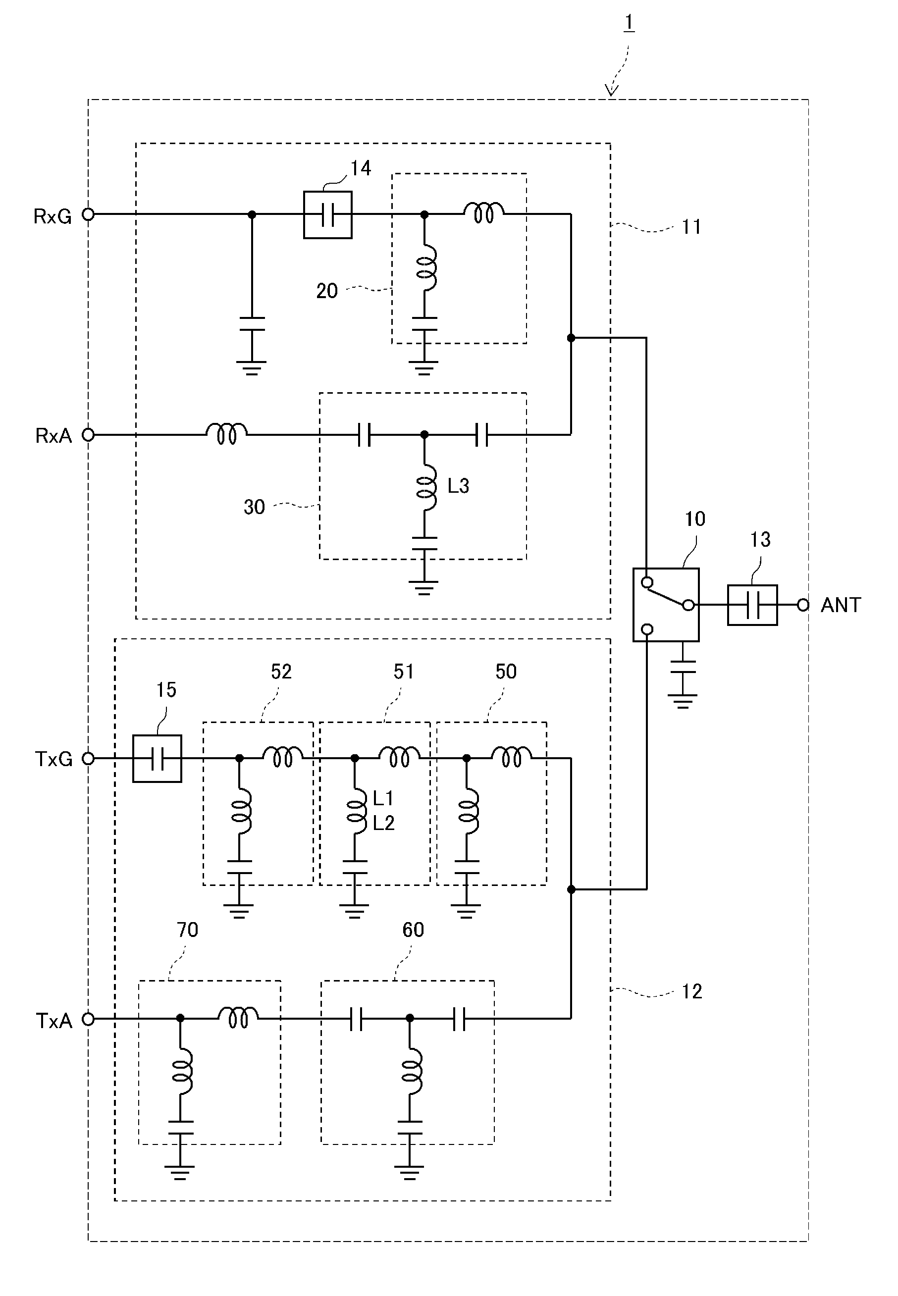
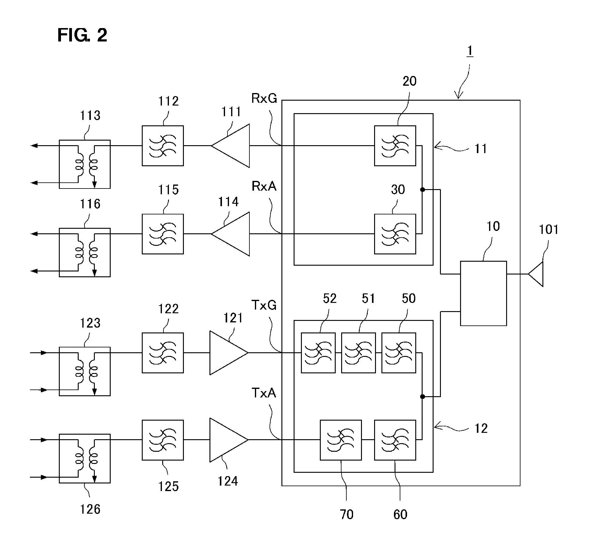
[0054]Hereinafter, a branching device according to preferred embodiments of the present invention will be described. The branching device according to a preferred embodiment of the present invention is used for communication using a wireless LAN. The branching device processes a first reception signal and a first transmission signal in a first frequency band and a second reception signal and a second transmission signal in a second frequency band that is located on a high-frequency wave side with respect to the first frequency band in this preferred embodiment. For example, the first frequency band is a 2.4 GHz band used in IEEE802.11b. For example, the second frequency band is a 5 GHz band used in IEEE802.11a. In addition, at the time of implementation, in addition to the first and second frequency bands, a circuit configuration in which a high-frequency signal in another frequency band is processed may be added to the branching device.

[0055]First, the configuration of a high-frequ...


PUM


Abstract

In a branching device, an LPF includes a first inductor arranged such that some conductor layers from among conductor layers are wound in a clockwise direction, and a second inductor arranged such that a conductor layer from among the conductor layers is wound in an counterclockwise direction. In addition, an HPF includes a third inductor arranged such that conductor layers are wound in the same clockwise direction as the first inductor. Therefore, when a high-frequency signal passes through the LPF, a winding direction is reversed. In addition, when a high-frequency signal passes through the HPF, a winding direction is reversed.

Description

BACKGROUND OF THE INVENTION[0001]1. Field of the Invention[0002]This invention relates to a branching device to process high-frequency signals in a plurality of frequency bands.[0003]2. Description of the Related Art[0004]In recent years, as a technique allowing a network to be easily established, a wireless LAN in which a LAN is established using radio waves has been developed. In the wireless LAN, there are a plurality of standards, such as IEEE802.11b, in which a 2.4 GHz band is used as a frequency band and IEEE802.11a in which a 5 GHz band is used as a frequency band. Therefore, a communication device used for the wireless LAN incorporates a branching device that is connected to an antenna and processes high-frequency signals in a plurality of frequency bands.[0005]For example, in Japanese Unexamined Patent Application Publication No. 2006-352532, a branching device (high-frequency module) is disclosed that includes a first diplexer on a receiving side, a second diplexer on a tr...

Claims


Application Information

Patent Timeline
Patent Type & Authority Applications(United States)
IPC IPC(8): H03H7/46
CPCH03H7/0115H03H7/1758H03H7/175H03H2001/0085H04B1/0057H03H7/465
Inventor HANAOKA, KUNITOSHI
Owner MURATA MFG CO LTD
Why Eureka
Try Eureka