Automobile bumper arrangement and modular bumper system

a bumper arrangement and modular technology, applied in the directions of bumpers, vehicle safety arrangments, transportation and packaging, etc., can solve the problems of low insurance classification, small flexibility in the design of the bumper crossbeam, and significant damage to the fender area, so as to improve the crash response, reduce weight and unit costs and tool costs, the effect of high rigidity

Active Publication Date: 2012-04-19
BENTELER AUTOMOBILTECHNIK GMBH
View PDF7 Cites 10 Cited by
  • Summary
  • Abstract
  • Description
  • Claims
  • Application Information

AI Technical Summary

Benefits of technology

[0018]According to an advantageous feature of the present invention, the extension may be a profile component, for example a profile component with a C-shaped cross-section. When the automobile bumper arrangement is constructed in several parts, the extension may be optimally adapted to the respective crash requirements of both offset crashes and side crashes. In addition, the fields of application are thereby optimized, while at the same time the weight and the unit costs and tool costs are significantly reduced. Accordingly, an automobile can be produced using identical parts, wherein an automobile bumper arrangement can be produced particularly cost-effectively while simultaneously improving the crash response.
[0019]According to an advantageous feature of the present invention, the extension is a component produced by forming. The component may be a sheet-metal component produced with different forming processes. For example, the sheet-metal component may be produced by rolling, by hot-rolling followed by press-hardening, or with other similar forming processes. A particularly high rigidity in the side region may be attained by annealing and/or hardening the ex

Problems solved by technology

When the degree of overlap with a barrier is very low, for example during the bumper-to-bumper test, the barrier used in a crash test may slide of the curved end section of the bumper crossbeam or the automobile may slides along the barrier, which may cause significant damage to the fender area.
This type of damage will result in a lower insurance classific

Method used


Image

  • Automobile bumper arrangement and modular bumper system
  • Automobile bumper arrangement and modular bumper system

Examples


Embodiment Construction

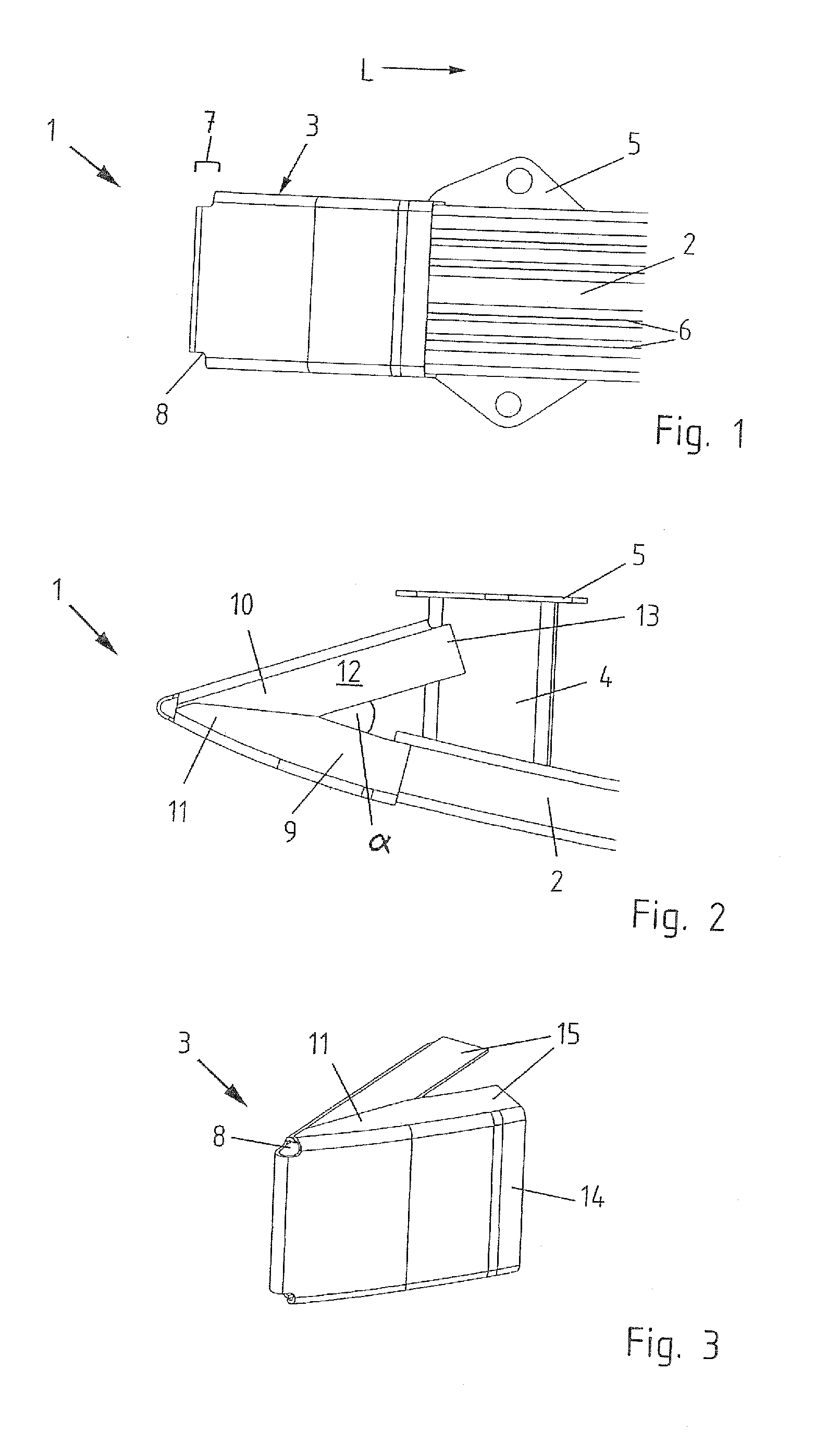
[0033]Throughout all the figures, same or corresponding elements may generally be indicated by same reference numerals. These depicted embodiments are to be understood as illustrative of the invention and not as limiting in any way. It should also be understood that the figures are not necessarily to scale and that the embodiments are sometimes illustrated by graphic symbols, phantom lines, diagrammatic representations and fragmentary views. In certain instances, details which are not necessary for an understanding of the present invention or which render other details difficult to perceive may have been omitted.

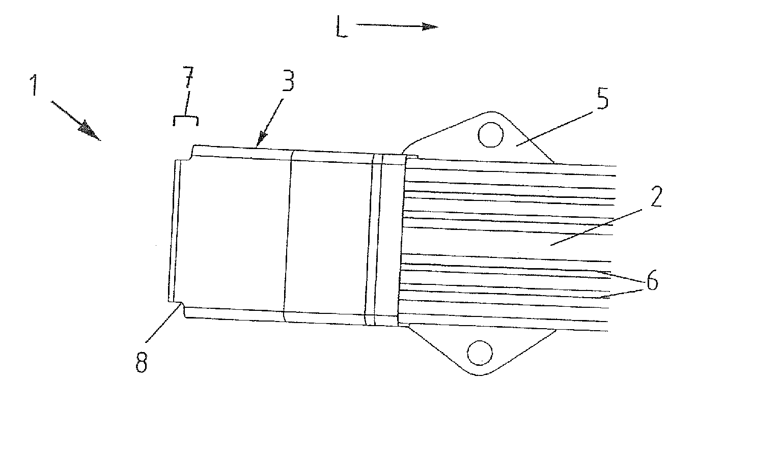
[0034]Turning now to the drawing, and in particular to FIG. 1, there is shown an automobile bumper arrangement 1 according to the invention in a frontal view. The automobile bumper arrangement 1 has a crossbeam 2, an extension 3 coupled to the crossbeam 2, as well as an unillustrated crash box 4 and a flange plate 5 coupled to the crash box 4. The flange plate 5 is used to a...


PUM


Abstract

An automobile bumper arrangement includes a crossbeam coupled to side rails of an automobile via crash boxes, wherein the crossbeam has extensions disposed at end sections which are laterally supported on a corresponding crash box. A modular bumper system has a crossbeam, an extension and a crash box coupled to a side rail of an automobile, wherein the crossbeam has a standardized length and a vehicle-specific width of a bumper can be attained by varying the length of the extension.

Description

CROSS-REFERENCES TO RELATED APPLICATIONS[0001]This application claims the priority of German Patent Application, Serial No. 10 2010 014 999.3-21, filed Apr. 14, 2010, pursuant to 35 U.S.C. 119(a)-(d), the content of which is incorporated herein by reference in its entirety as if fully set forth herein.BACKGROUND OF THE INVENTION[0002]The present invention relates to an automobile bumper arrangement a modular bumper system for an automobile.[0003]The following discussion of related art is provided to assist the reader in understanding the advantages of the invention, and is not to be construed as an admission that this related art is prior art to this invention.[0004]Bumper systems of automobiles have particular importance in view of current legal requirements in the area of low-speed tests and high-speed tests, because the design of a bumper system has a direct impact on the type of damage and the monetary amount of damages of an automobile.[0005]The type of damage and the monetary ...

Claims


Application Information

Patent Timeline
IPC IPC(8): B60R19/26
CPCB60R19/18B60R2019/247B60R19/34B60R19/24
Inventor PAARE, MIRKOSTAZNIKIEWICZ, DARIUSZMULLER, OLIVERSEIDL, ENRICO
Owner BENTELER AUTOMOBILTECHNIK GMBH
Why Eureka
Try Eureka