Attachment rail system for household appliance

a technology for attaching rails and household appliances, which is applied in the direction of domestic stoves or ranges, lighting and heating apparatus, heating types, etc. it can solve the problems of unsightly alignment, difficult and time-consuming positioning of household appliances, and high quality of cabinet or other structures, so as to facilitate the trial and error method, reduce the likelihood of installation, and facilitate the effect of installation

Active Publication Date: 2012-06-14
BSH HOME APPLIANCES CORP
View PDF28 Cites 6 Cited by
  • Summary
  • Abstract
  • Description
  • Claims
  • Application Information

AI Technical Summary

Benefits of technology

[0005]The invention recognizes that it is desirable to provide an attachment system that is easy to install and that facilitates the trial and error method that is often required to properly position an appliance in a cabinet or other structure. Exemplary embodiments of the invention provide an atta

Problems solved by technology

Many of these cabinets or other structures are high quality, visually pleasing and expensive.
It can be difficult and time consuming to position a household appliance such as an oven in a built-in installation using conventional attachment systems.
This leads

Method used


Image

  • Attachment rail system for household appliance
  • Attachment rail system for household appliance
  • Attachment rail system for household appliance

Examples


Embodiment Construction

[0018]The invention is described herein with reference to the accompanying drawings in which exemplary embodiments of the invention are shown. The invention may, however, be embodied in many different forms and should not be construed as limited to the embodiments set forth herein.

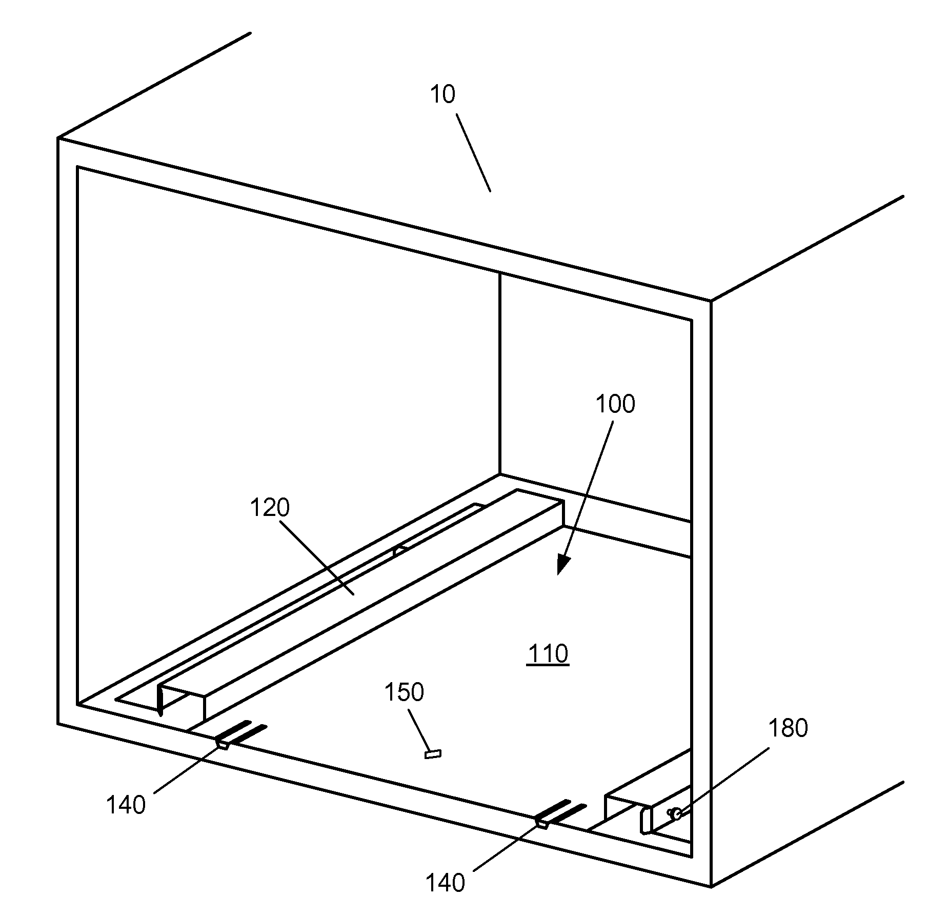
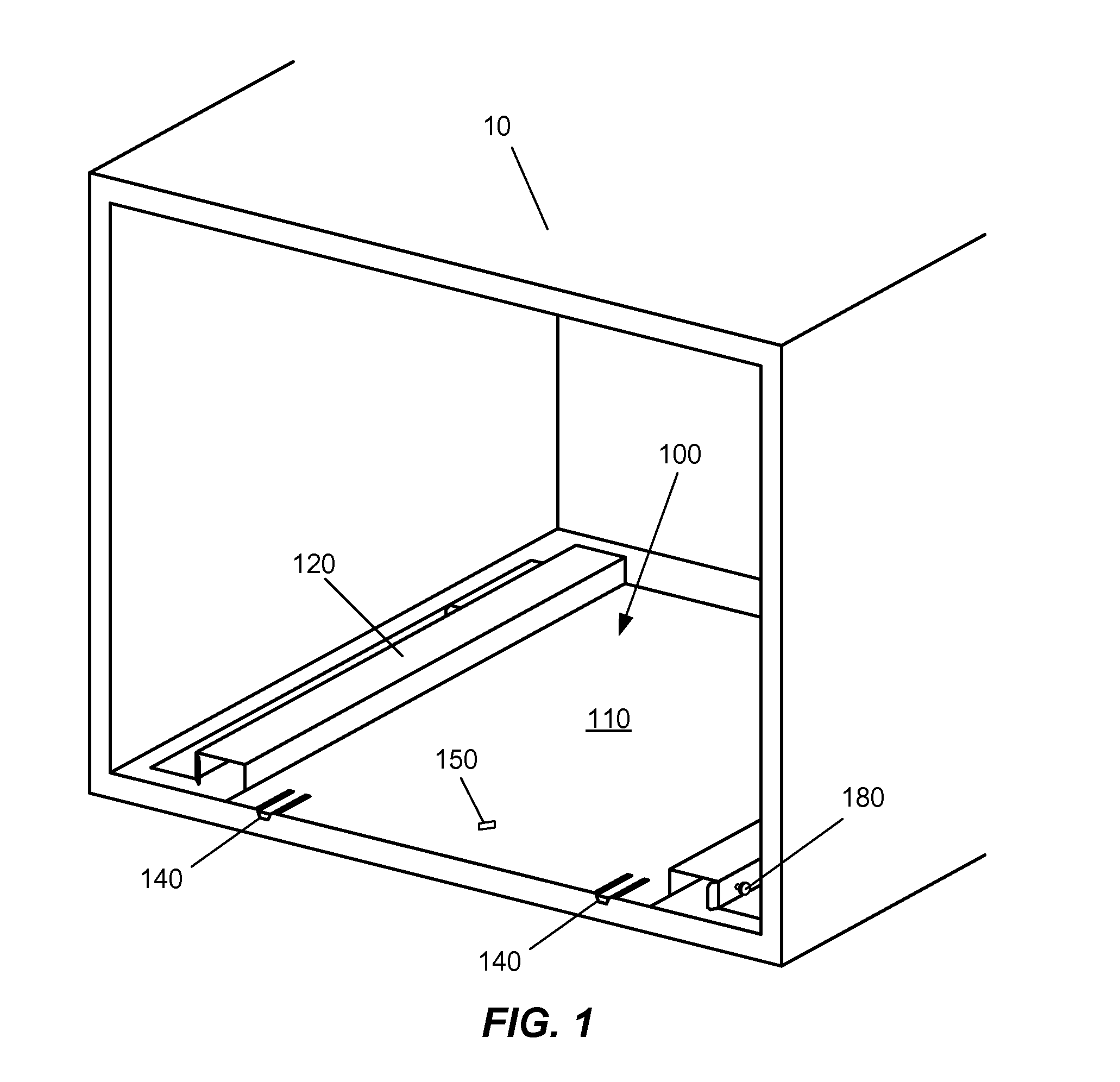
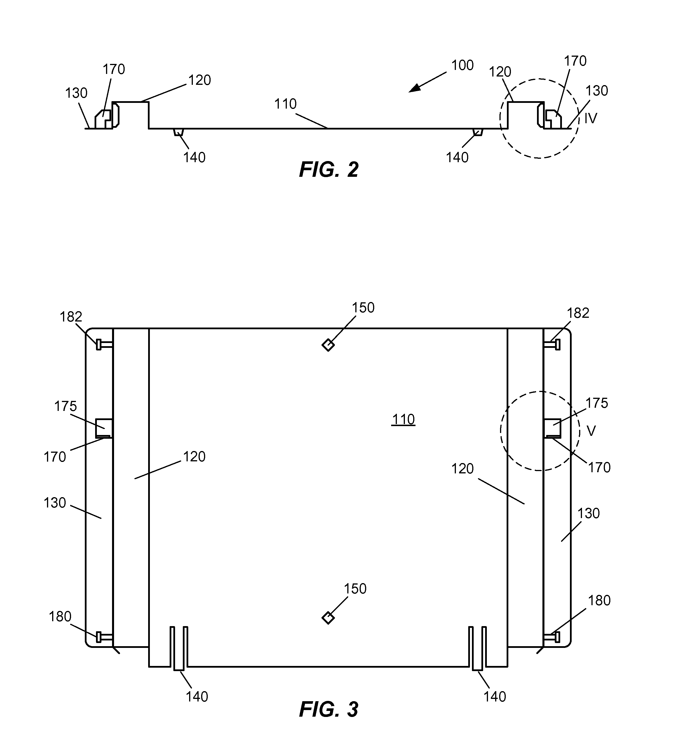
[0019]FIG. 1 shows a cabinet 10 having an internal space that can be occupied by a household appliance. FIG. 1 shows a positioning base 100 located in the internal space of cabinet 10. Positioning base 100 has several locating features that assist in properly locating positioning base 100 in cabinet 10. In this example, positioning base 100 has two edge guides 140 at its front edge which overhang a front edge of a support surface, or shelf, of cabinet 10. Positioning base 100 is pushed rearwardly into the internal space of cabinet 10 until edge guides 140 contact the front edge of the support surface or cabinet. In this example, positioning base 100 also has two locating diamonds 150 that are holes in a ma...


PUM


Abstract

An attachment system for attaching a household appliance to a cabinet. The system includes a base having a main body for attaching to the cabinet, front and rear lugs that project substantially horizontally from and are elevated relative to a support area of the cabinet, and a rail catch projecting from the positioning base; and a rail adapted to be attached to a side of the appliance. The rail has a lip that engages the rail catch and limits movement of the rail in a vertical direction, a rear engagement area that engages the rear lug in the installed position, and a front engagement area that engages the front lug in an installing position and in the installed position. The front engagement area has a notch in which the front lug rests in the installed position, and a ramp sloping downward from the notch toward the rear engagement area.

Description

FIELD OF THE INVENTION[0001]The invention is directed to an attachment rail system for a household appliance, and, more particularly, to an attachment rail system that facilitates installation and removal of the appliance from a cabinet.[0002]An example of an application for the invention is an attachment rail system for a cabinet mounted household oven.BACKGROUND OF THE INVENTION[0003]Many home appliances, such as, for example, ovens, are mounted in cabinets or other structures. Many of these cabinets or other structures are high quality, visually pleasing and expensive. It can be difficult and time consuming to position a household appliance such as an oven in a built-in installation using conventional attachment systems. Often the support surface (such as a shelf) on which the appliance is positioned is not level and / or is not parallel / perpendicular to the edges of the cabinet that are visible after the installation is complete. This leads to either unsightly alignment or a diffi...

Claims


Application Information

Patent Timeline
IPC IPC(8): A47B88/04F16M13/00
CPCF24C15/30A47B88/12
Inventor CURRLE, ANDREASSHERBERT, KEVIN W.TAYLOR, JAMES O'NEAL
Owner BSH HOME APPLIANCES CORP
Why Eureka
Try Eureka