Unlock instant, AI-driven research and patent intelligence for your innovation.

Filtration systems for chemical fluids

Inactive Publication Date: 2012-07-19
GE OIL & GAS UK LTD
View PDF5 Cites 1 Cited by
  • Summary
  • Abstract
  • Description
  • Claims
  • Application Information

AI Technical Summary

Benefits of technology

[0008]According to another embodiment of the present invention, there is provided a method of producing a filtration system for filtering a chemical fluid used in a subsea hydrocarbon extraction well. The method comprises providing a filter arrangement, and connecting opposite ends of the filter arrangement to respective fluid flow passageways by hydraulically operated connectors using a remotely operated vehicle which operates the connectors in a hot stab manner.
[0008]According to another embodiment of the present invention, there is provided a method of producing a filtration system for filtering a chemical fluid used in a subsea hydrocarbon extraction well. The method comprises providing a filter arrangement, and connecting opposite ends of the filter arrangement to respective fluid flow passageways by hydraulically operated connectors using a remotely operated vehicle which operates the connectors in a hot stab manner.

Problems solved by technology

Flow lines and pipelines carrying hydrocarbons are subject to build-up of hydrates (which are crystalline in nature) which impede and may block the flow of hydrocarbons if not prevented or reduced.
Furthermore, the method of mounting the current filter module in a horizontal configuration severely restricts the access for an ROV.
Thus the current process of MEG filter replacement is difficult, time consuming and therefore expensive.

Method used


Image

  • Filtration systems for chemical fluids
  • Filtration systems for chemical fluids
  • Filtration systems for chemical fluids

Examples


Embodiment Construction

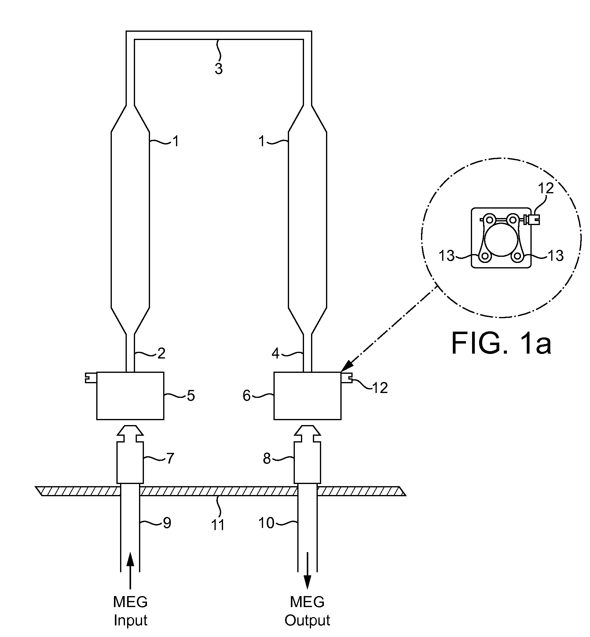
[0015]FIG. 2 (in which items which correspond with items in FIG. 1 have the same reference numerals as in FIG. 1) illustrates an application of an embodiment of the present invention which includes the introduction of annulus flowline hydraulically operated connectors 14 and 15 to replace connectors 5 and 6. Each of connectors 14 and 15 is, by way of example, a Vetco Gray 2 1 / 16″ flowline hydraulic connector part number A110312-9, to connect the MEG filter arrangement to the semi-permanent infrastructure. These connectors require hydraulic actuation, which is via hydraulic pipes 16 and 17 respectively, connected to a vertically mounted ROV hot stab connector portion 18 at the top of the 180 degree loop, that is on the apex region 3 of the filter arrangement. The hydraulic connectors 14 and 15 are self-sealing, thus preventing the ingress of seawater and the expulsion of MEG during filter arrangement change. Each connector has a latch mechanism which is hydraulically driven open and ...


PUM


Abstract

A method of producing a filtration system for filtering a chemical fluid used in a hydrocarbon extraction well is provided. The method comprises providing a filter arrangement comprising an inlet end and an outlet end, connecting the inlet end to a first fluid flow passageway using a first hydraulically operated connector, and connecting the outlet end to a second fluid flow passageway using a second hydraulically operated connector.

Description

BACKGROUND OF THE INVENTION[0001]1. Field of the Invention[0002]Embodiments of the present invention relate to filtration systems for chemical fluids, in particular chemical fluids used in hydrocarbon extraction wells.[0003]2. Description of the Prior Art[0004]Flow lines and pipelines carrying hydrocarbons are subject to build-up of hydrates (which are crystalline in nature) which impede and may block the flow of hydrocarbons if not prevented or reduced. It is standard practice to inject mono ethylene glycol (MEG), which is a hydrate inhibitor, into such flow lines and pipelines for the prevention of hydrate formation and for the absorption of moisture. This process is normally carried out, in downtime, when production hydrocarbon fluid is not passing through the flow line or pipeline concerned. In offshore subsea control systems, the MEG is typically injected into an umbilical topside before being distributed through the subsea control system via MEG injection valves which are moun...

Claims


Application Information

Patent Timeline
IPC IPC(8): E21B43/08E21B41/00E21B41/04E21B23/00
CPCE21B43/01E21B43/00
Inventor MCCLURE, ANDREW JAMES
Owner GE OIL & GAS UK LTD
Features
  • R&D
  • Intellectual Property
  • Life Sciences
  • Materials
  • Tech Scout
  • Unparalleled Data Quality
  • Higher Quality Content
  • 60% Fewer Hallucinations
Learn More