Floating vertical axis wind turbine module system and method

a vertical axis, wind turbine technology, applied in vessel construction, renewable energy generation, greenhouse gas reduction, etc., can solve the problems of increasing the cost of offshore crane barges and services, and increasing the cost of offshore installation, so as to improve the securing and stability of the system and optimize the effect of wind energy

Inactive Publication Date: 2012-08-16
TECH FRANCE SA
View PDF1 Cites 22 Cited by
  • Summary
  • Abstract
  • Description
  • Claims
  • Application Information

AI Technical Summary

Benefits of technology

[0014]However, the above examples of prior publications do not address a wind energy system that has multiple mooring points that may be preferred for better securing and stability of the system, and still allow the system to be oriented to varying wind directions for optimizing wind energy.
[0015]There remains a need for an improved system and method for a wind energy system with a multipoint mooring system.
[0016]The disclosure provides a wind energy system with one or more floating modules having at least two vertical wind turbines mounted thereon. A multipoint mooring system couples the floating module to a seabed, the mooring system having at least two mooring points with at least two

Problems solved by technology

Thus, massive structures are being and have been built—with the attendant expense.
Offshore crane barges and services can be expensive.
When considering multiple turbine units, the multiple lifts, and crane assets deployed, it can add considerable cost to the offshore installation when compared to land-based installation, and therefore affect overall commercial viability of the offshore wind turbine installation.
Further, conventional horizontal axis wind turbines need to be installed at sites large distances apart as the shedding vortices from the rotating blades interferes with the next downwind turbine thus affecting performance and power output.
In the offshore environment, this spacing of turbines means large numbers of significantly separated structures are required to construct the overall wind farm, which involves considerable cost.
Thus, large numbers of turbines requi

Method used


Image

  • Floating vertical axis wind turbine module system and method
  • Floating vertical axis wind turbine module system and method
  • Floating vertical axis wind turbine module system and method

Examples


Embodiment Construction

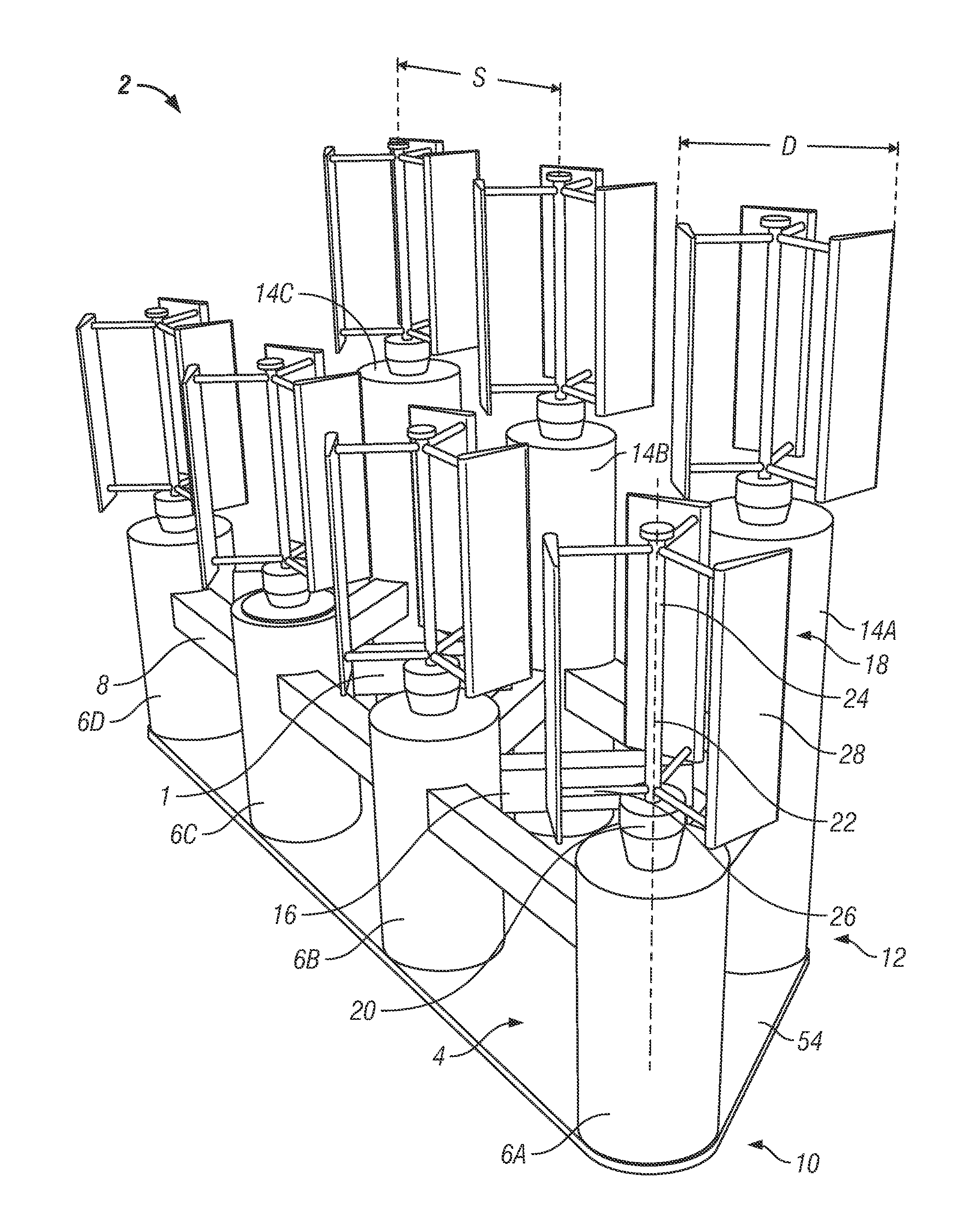
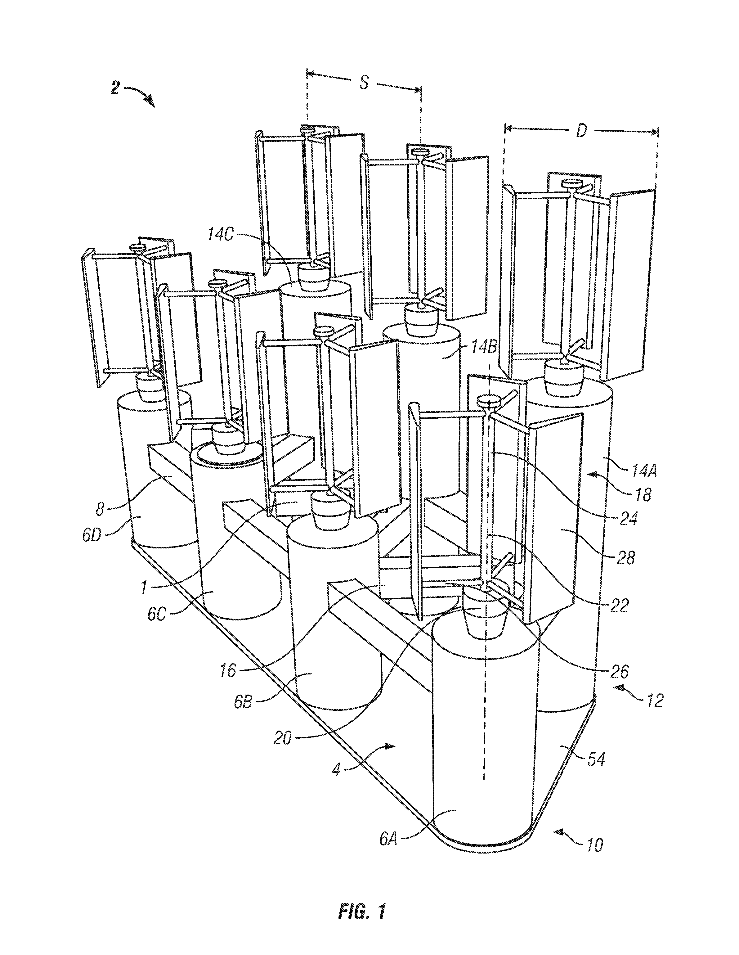
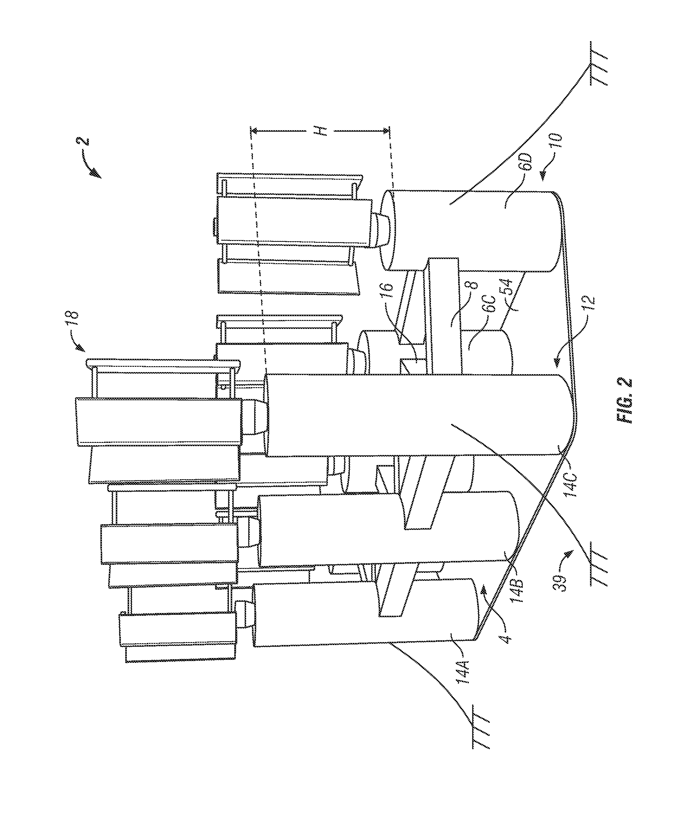
[0046]The Figures described above and the written description of specific structures and functions below are not presented to limit the scope of what Applicant has invented or the scope of the appended claims. Rather, the Figures and written description are provided to teach any person skilled in the art how to make and use the inventions for which patent protection is sought. Those skilled in the art will appreciate that not all features of a commercial embodiment of the inventions are described or shown for the sake of clarity and understanding. Persons of skill in this art will also appreciate that the development of an actual commercial embodiment incorporating aspects of the present inventions will require numerous implementation-specific decisions to achieve the developer's ultimate goal for the commercial embodiment. Such implementation-specific decisions may include, and likely are not limited to, compliance with system-related, business-related, government-related and other...


PUM

PropertyMeasurementUnit
Lengthaaaaaaaaaa
Wind energyaaaaaaaaaa
Heightaaaaaaaaaa

Abstract

The disclosure provides a wind energy system with one or more floating modules having at least two vertical wind turbines mounted thereon. A multipoint mooring system couples the floating module to a seabed, the mooring system having at least two mooring points with at least two lines positioned at location s around the floating module with the wind turbines. A rotation system is coupled to the floating module and adapted to twist the floating module relative to wind direction while the multipoint mooring system is coupled between the seabed and the floating module. The rotation system can include induced gyroscopic torque from counter-rotating wind turbines and a self-adjusting induced gyroscopic torque differential from varying wind directions. Other rotation systems can include winches and translating assemblies that can be activated to tighten or loosen mooring lines in the multipoint mooring system coupled to the floating module in a catenary manner.

Description

CROSS REFERENCE TO RELATED APPLICATIONS[0001]This application is a national phase application of PCT / US2010 / 052998 filed Oct. 18, 2010 entitled “Floating Vertical Axis Wind Turbine Module System and Method”, and claims the benefit of U.S. Provisional Application No. 61 / 253,562, filed Oct. 21, 2009, entitled “Floating Vertical Axis Wind Turbine Module System and Method”.STATEMENT REGARDING FEDERALLY SPONSORED RESEARCH OR DEVELOPMENT[0002]Not applicable.REFERENCE TO APPENDIX[0003]Not applicable.BACKGROUND OF THE INVENTION[0004]1. Field of the Invention[0005]The disclosure relates generally to a system and method for offshore wind turbines. More specifically, the disclosure relates to a system and method for a floating wind turbine module.[0006]2. Description of the Related Art[0007]The use of offshore wide turbines is becoming an increasingly feasible and desirable form of power generation. A current premise in implementing wind turbines is “the bigger, the better”—the larger the turb...

Claims


Application Information

Patent Timeline
IPC IPC(8): F03D3/00B23P6/00F03D11/04
CPCF03D3/02F05B2240/93Y10T29/49718Y02E10/74F05B2240/95F03D13/25Y02E10/727F03D3/00
Inventor HARRIS, PETER GRAHAMO'SULLIVAN, JAMES
Owner TECH FRANCE SA
Why Eureka
Try Eureka