Fuel injector

a fuel injector and fuel technology, applied in the direction of machines/engines, mechanical equipment, lighting and heating apparatus, etc., can solve the problems of large amount of nox generated, unstable flame, and reduced fuel consumption, and achieve high ignitability of the pilot injector, improve combustion efficiency, and improve combustion efficiency

Active Publication Date: 2012-12-06
KAWASAKI HEAVY IND LTD +1
View PDF14 Cites 37 Cited by
  • Summary
  • Abstract
  • Description
  • Claims
  • Application Information

AI Technical Summary

Benefits of technology

[0008]The present invention addresses the above described conditions, and an object of the present invention is to provide a fuel injector capable of realizing the NOx reduction by adequately mixing the air and the fuel when the output of the gas turbine engine is intermediate or high, that is, when the main injector is operating, without increasing the complexity of devices and control mechanisms.

Problems solved by technology

Meanwhile, the amount of CO2 emission of the gas turbine engine, that is, fuel consumption decreases as an exhaust gas at an exit of a combustor increases in temperature.
Therefore, a large amount of NOx is generated from the local regions where the flame temperature is high.
Meanwhile, according to the lean premix combustion method, in a case where the output of the gas turbine engine is low and the fuel-air ratio is low, the flame is unstable and incomplete combustion tends to occur as compared to a case where the fuel is directly sprayed to the combustion chamber.
Therefore, although the amount of NOx emission is generally not so large, the main pre-mixture tends to cause the incomplete combustion, and the combustion efficiency tends to be low.
However, the amount of NOx emission tends to be large.
Forming the fuel injection holes corresponding to each of a plurality of fuel supply systems as above increases structural complexity of the fuel injector.
However, providing the cooling structures respectively for the plurality of fuel supply systems of the fuel injection holes within a limited space in the main injector extremely increases the structural complexity of the main injector.
Moreover, in a case where the fuel injection holes to be used are switched in accordance with the output, a control mechanism is required, and it is extremely difficult to secure reliability for ensuring appropriate selection of the fuel injection holes in any scene.

Method used


Image

  • Fuel injector
  • Fuel injector
  • Fuel injector

Examples


Embodiment Construction

[0035]Hereinafter, preferred embodiments of the present invention will be explained in reference to the drawings.

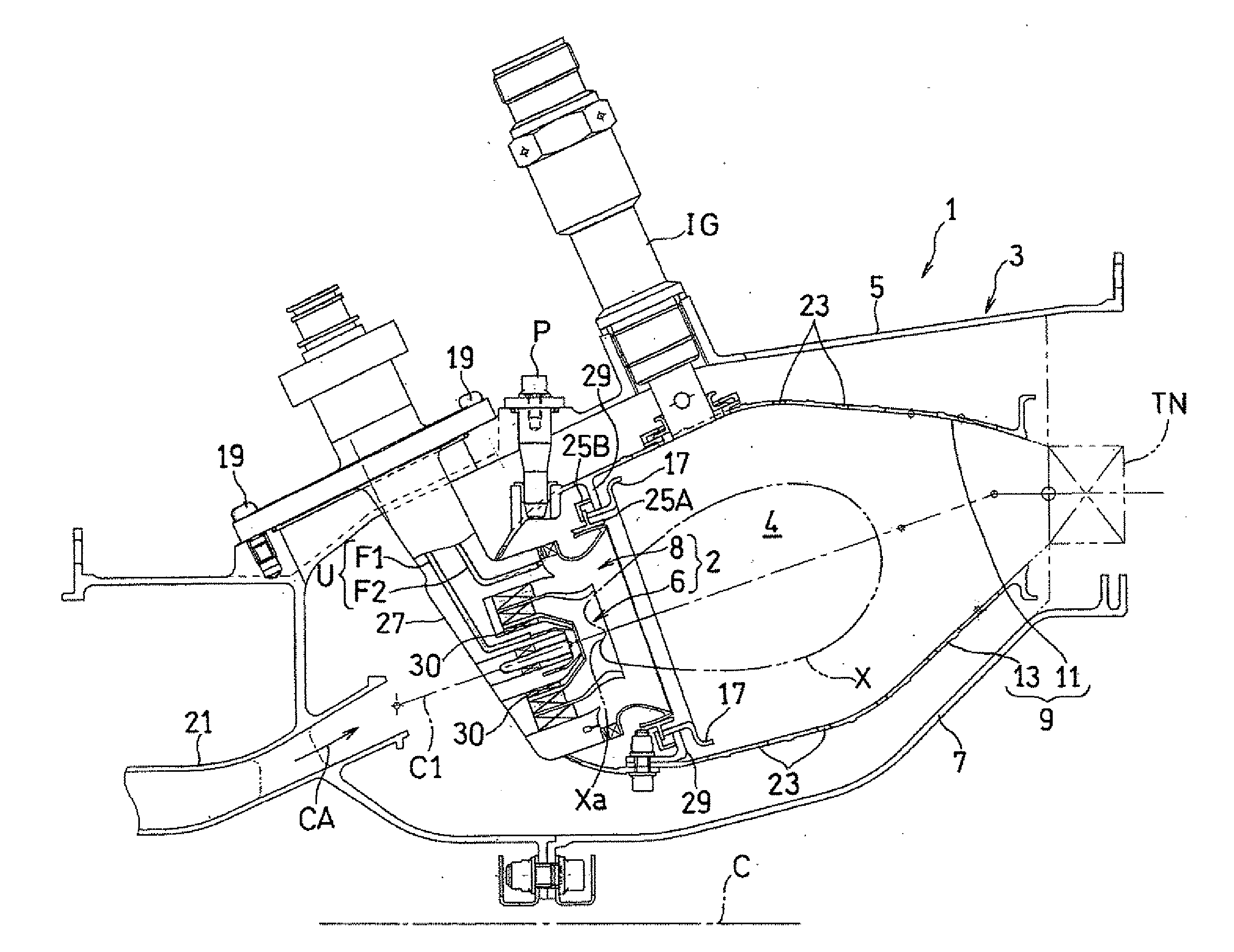
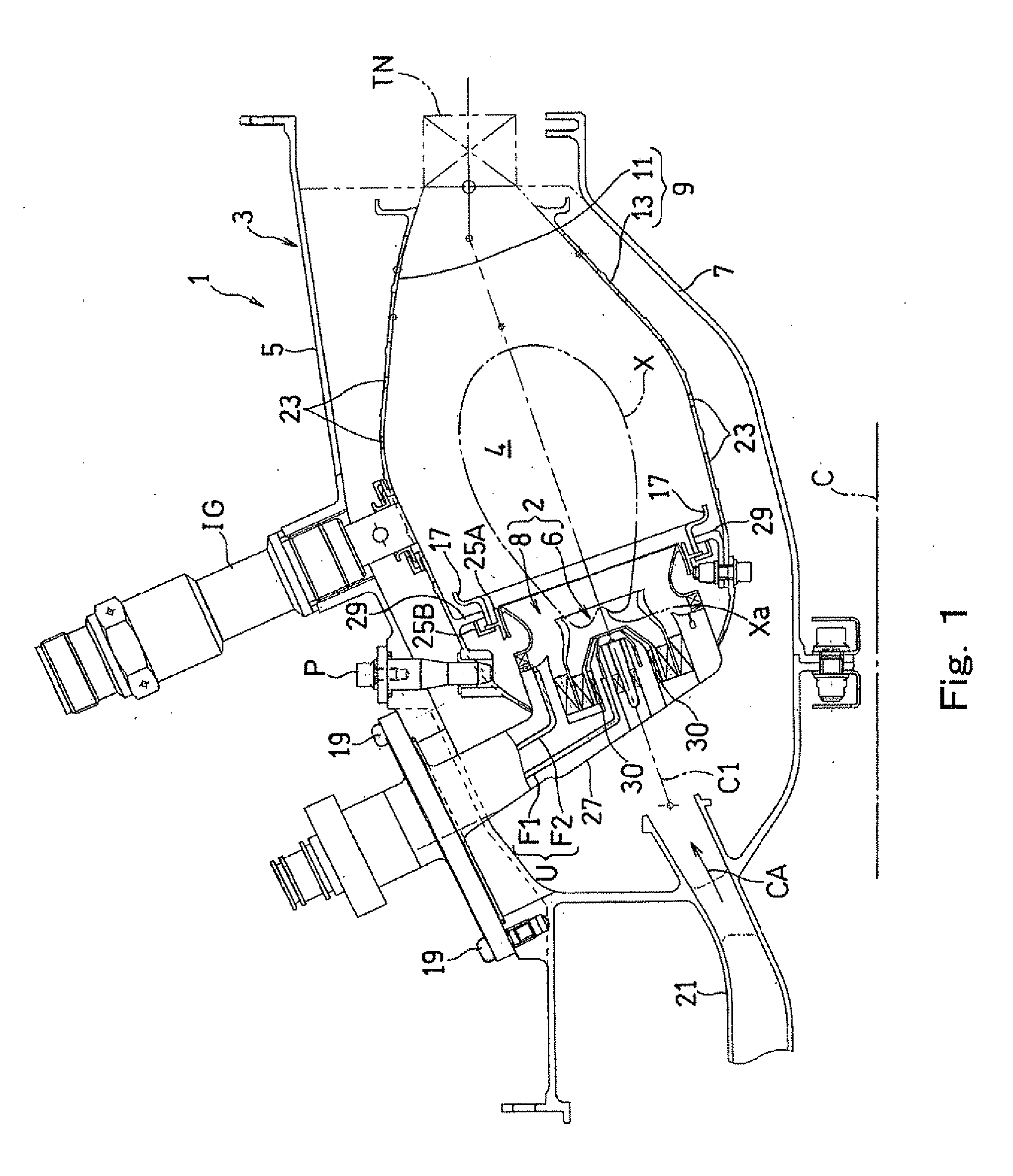
[0036]FIG. 1 shows a combustor 1 of a gas turbine engine including a fuel injector 2 according to one embodiment of the present invention. The combustor 1 mixes fuel with compressed air supplied from a compressor (not shown) of the gas turbine engine, combusts the obtained mixture, and supplies a high temperature and pressure combustion gas, generated by this combustion, to drive the turbine.

[0037]The combustor 1 is an annular type, and an annular outer casing 5 and an annular inner casing 7 provided inside the annular outer casing 5 constitute a combustor housing 3 including an annular internal space. The annular outer casing 5 and the annular inner casing 7 are provided coaxially with an engine rotation central axis C. In the annular internal space of the combustor housing 3, an annular combustor liner 9 is provided coaxially with the combustor housing 3. The combustor ...


PUM


Abstract

A fuel injector includes: a pilot injector configured to spray fuel so as to form a first combustion region in a combustion chamber; and a main injector provided coaxially with the pilot injector so as to surround the pilot injector and configured to supply a fuel-air mixture that is a mixture of the fuel and air to form a second combustion region in the combustion chamber, wherein the main injector includes: a first inflow channel through which the air having a major flow component in an axial direction is taken; a second inflow channel through which the air having a major flow component in a radial direction is taken and which causes the air therein to meet the air from the first inflow channel; and a main fuel injecting portion configured to inject the fuel only to the second inflow channel.

Description

BACKGROUND OF THE INVENTION[0001]1. Field of the Invention[0002]The present invention relates to a fuel injector used in, for example, a gas turbine engine and including a combined fuel injector configured by combining a plurality of fuel nozzles, and particularly to a main injector of the fuel injector.[0003]2. Description of the Related Art[0004]In recent years, in consideration of the environment, there is a need for a reduction of NOx (nitrogen oxide) emitted from gas turbine engines. The NOx to be emitted from the gas turbine engine is generated mainly by oxidization of nitrogen in inflow air when fuel is supplied to the inflow air and combusted at high temperature. Meanwhile, the amount of CO2 emission of the gas turbine engine, that is, fuel consumption decreases as an exhaust gas at an exit of a combustor increases in temperature. Therefore, to reduce the CO2, the fuel needs to be combusted at high temperature by increasing a fuel-air ratio. According to a fuel nozzle of a c...

Claims


Application Information

Patent Timeline
Patent Type & Authority Applications(United States)
IPC IPC(8): F02C7/22
CPCF23R3/14Y02T50/675F23R3/286Y02T50/60
Inventor MATSUYAMA, RYUSUKEKOBAYASHI, MASAYOSHIODA, TAKEOHORIKAWA, ATSUSHIHAYASHI, SHIGERUSHIMODAIRA, KAZUOMATSUURA, KAZUAKIYAMADA, HIDESHIKUROSAWA, YOUJIFUJIWARA, HITOSHI
Owner KAWASAKI HEAVY IND LTD
Why Eureka
Try Eureka