Autofocus imaging

a technology of autofocus and imaging system, which is applied in the field of digital pathology, can solve the problems of insufficient performance of the autofocus function, and achieve the effect of improving robustness and accuracy

Active Publication Date: 2013-03-07
KONINKLIJKE PHILIPS ELECTRONICS NV
View PDF8 Cites 8 Cited by
  • Summary
  • Abstract
  • Description
  • Claims
  • Application Information

AI Technical Summary

Benefits of technology

[0014]In other words, the object of interest may be illuminated with a beam comprising a set of directions of propagation, such that the angle of these directions of propagation is larger than the angle sub-tended by the detection aperture of the autofocus imaging sensor. In this way light reflected from various surfaces (air, cover slip, cover slip-tissue layer, tissue layer-slide, slide-air) may not end up at the autofocus image sensor. In fact, all low object spatial frequencies may be blocked and only signal emanating from the tissue (which has sufficiently high spatial frequencies) may be detected at the autofocus image sensor. This may improve the robustness and accuracy that the axial position of the tissue layer can be measured.

Problems solved by technology

However, the performance of the autofocus function may be insufficient.

Method used


Image

  • Autofocus imaging
  • Autofocus imaging
  • Autofocus imaging

Examples


Embodiment Construction

[0033]The illustration in the drawings is schematically. In different drawings, similar or identical elements are provided with the same reference numerals.

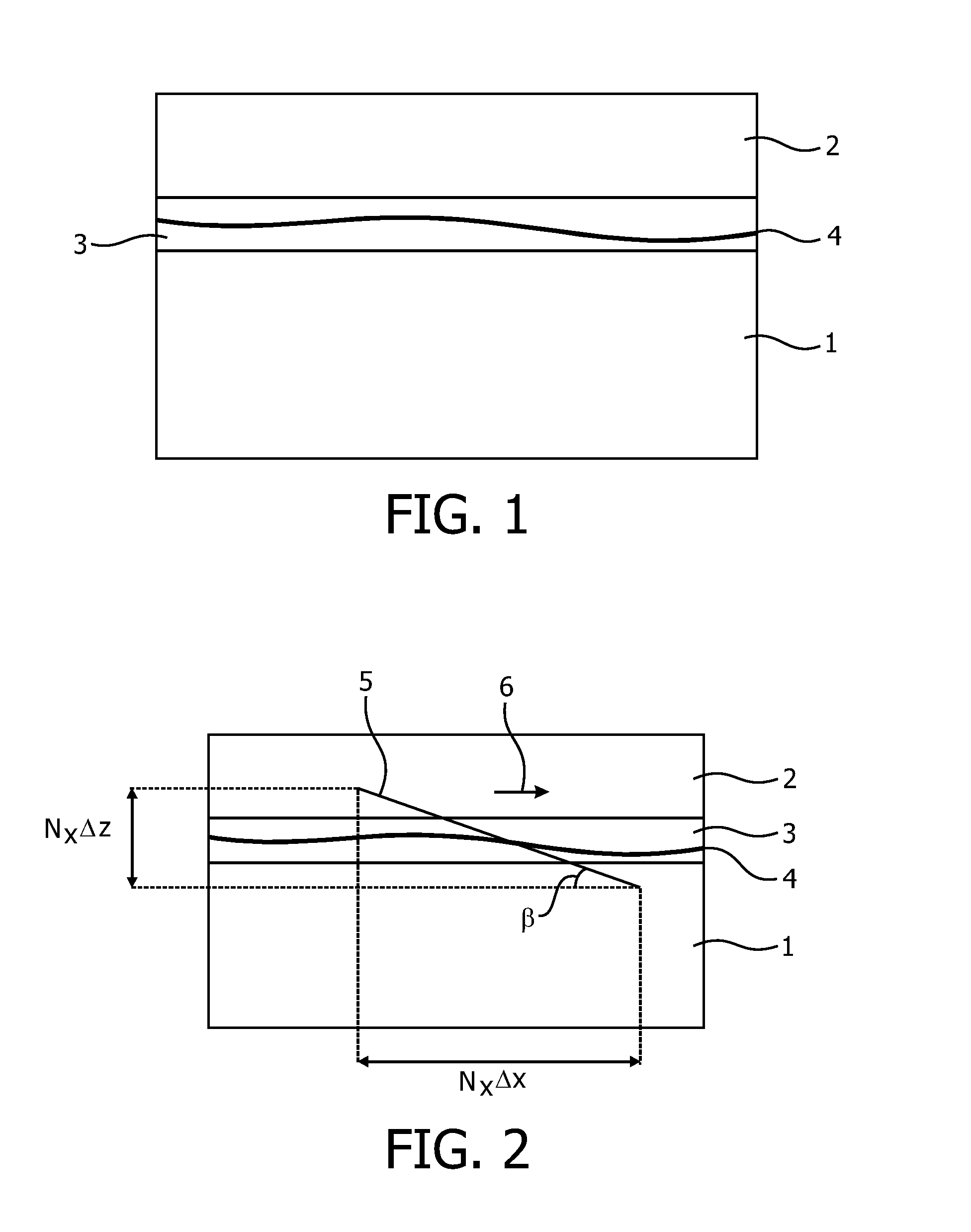
[0034]In the following, the character prime (′) associated to a symbol will mean that the image space is considered (e.g. sensor reference) while a symbol without prime character will mean that the object space is considered (typically the sample reference). For example, when the angle Beta prime (β′) will be used in this decription, a rotation in image space, and, as will be described more specifically, a rotation of the physical sensor, will be indicated. Also, an angle Beta (β without prima) will indicate a rotation in object space, and as will be described more specifically a rotation of an oblique cross section of the sample that is imaged by the autofocus sensor.

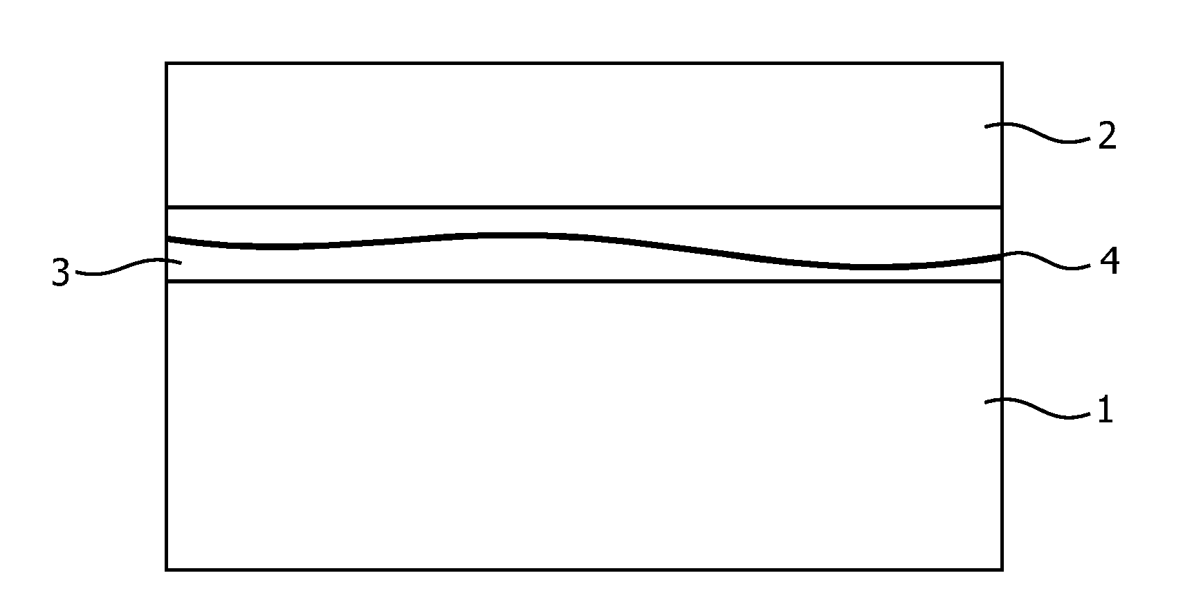
[0035]FIG. 1 shows a schematic cross-section of a tissue slide assembly, comprising a microscope slide 1, having a typical thickness of 1 mm, a cover slip 2, with a...


PUM


Abstract

The present invention relates to the field of digital pathology and in particular to whole slide scanners. Autofocus imaging can be performed by sampling a first number of pixels of a primary image sensor and sampling a second number of pixels of an autofocus image sensor, wherein the second number is between one quarter and three quarters of the first number. Thus, continuous autofocus for rapid light scanning may be provided based on an additional image sensor that is tilted with respect to the optical axis.

Description

FIELD OF THE INVENTION[0001]The present invention relates to the field of digital pathology, notably. In particular, the present invention relates to an autofocus imaging system for a microscope, a microscope comprising an autofocus imaging system, a method for autofocus imaging of a microscope, a computer-readable medium and a program element.BACKGROUND OF THE INVENTION[0002]In digital pathology and particular in the case of whole slide scanning, specimens are sliced and imaged for analysis purposes as well as teaching purposes. Line sensors may be used for scanning a whole tissue slide. These slide scanners may perform a continuous mechanical scanning, thereby reducing stitching problems and allowing for the use of so-called time delay integration (TDI) line sensors in order to accommodate for low brightness of the illumination.[0003]For focusing focus maps may be used. Before the actual scanning the optimum focus position is determined at a number of positions on the slide. This ...

Claims


Application Information

Patent Timeline
Patent Type & Authority Applications(United States)
IPC IPC(8): G03B13/00H04N7/18
CPCG02B21/241G02B21/245H04N23/673H04N3/1581G02B21/36H04N23/45
Inventor HULSKEN, BASSTALLINGA, SJOERD
Owner KONINKLIJKE PHILIPS ELECTRONICS NV
Why Eureka
Try Eureka