Single focus lens system and photographing apparatus including the same

Active Publication Date: 2013-03-07
SAMSUNG ELECTRONICS CO LTD
View PDF2 Cites 19 Cited by
  • Summary
  • Abstract
  • Description
  • Claims
  • Application Information

AI Technical Summary

Benefits of technology

[0008]The invention provides a single focus lens syst

Problems solved by technology

However, users demand, in addition to high optical performance, a compact lens sy

Method used


Image

  • Single focus lens system and photographing apparatus including the same
  • Single focus lens system and photographing apparatus including the same
  • Single focus lens system and photographing apparatus including the same

Examples


Example

Embodiment 1

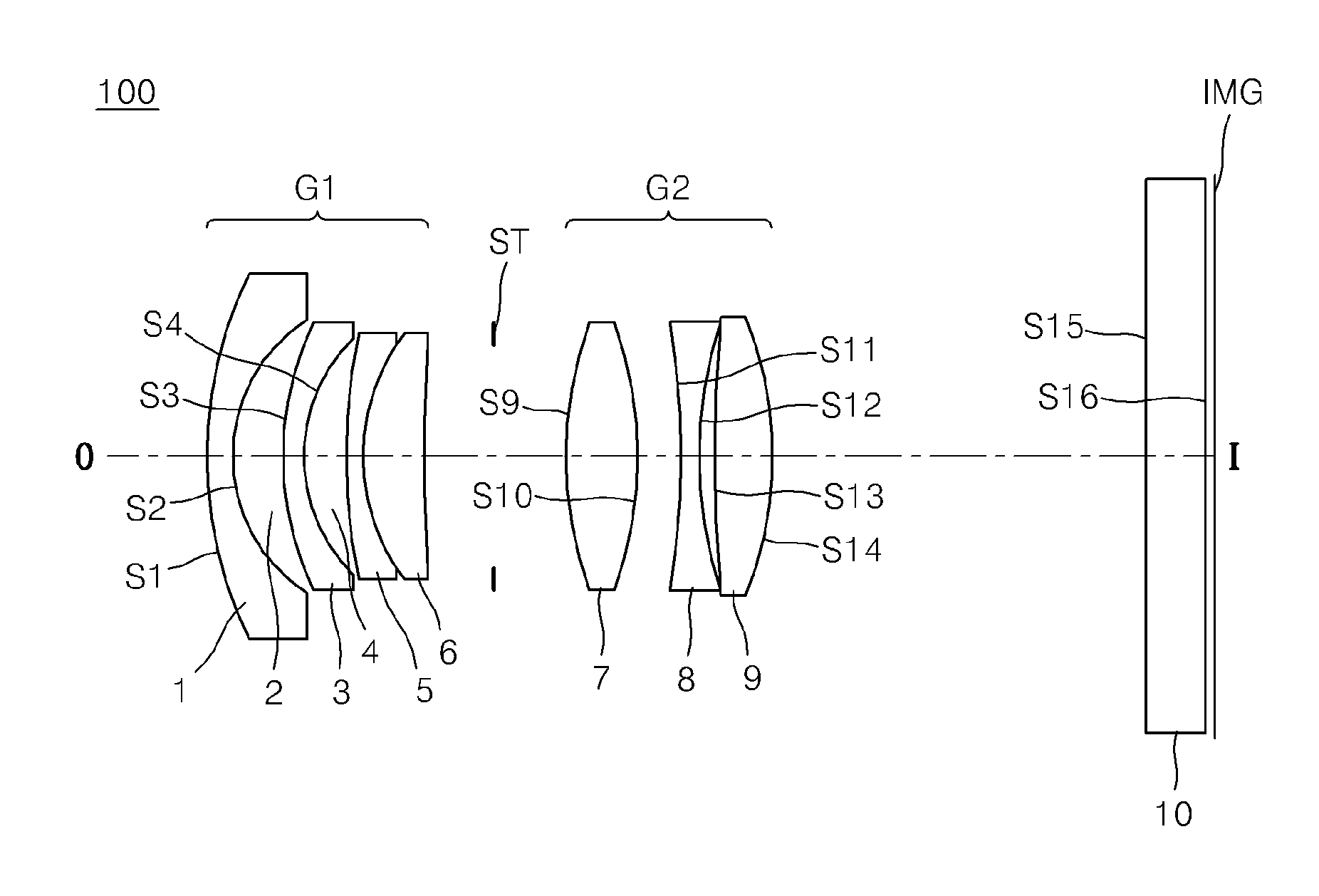
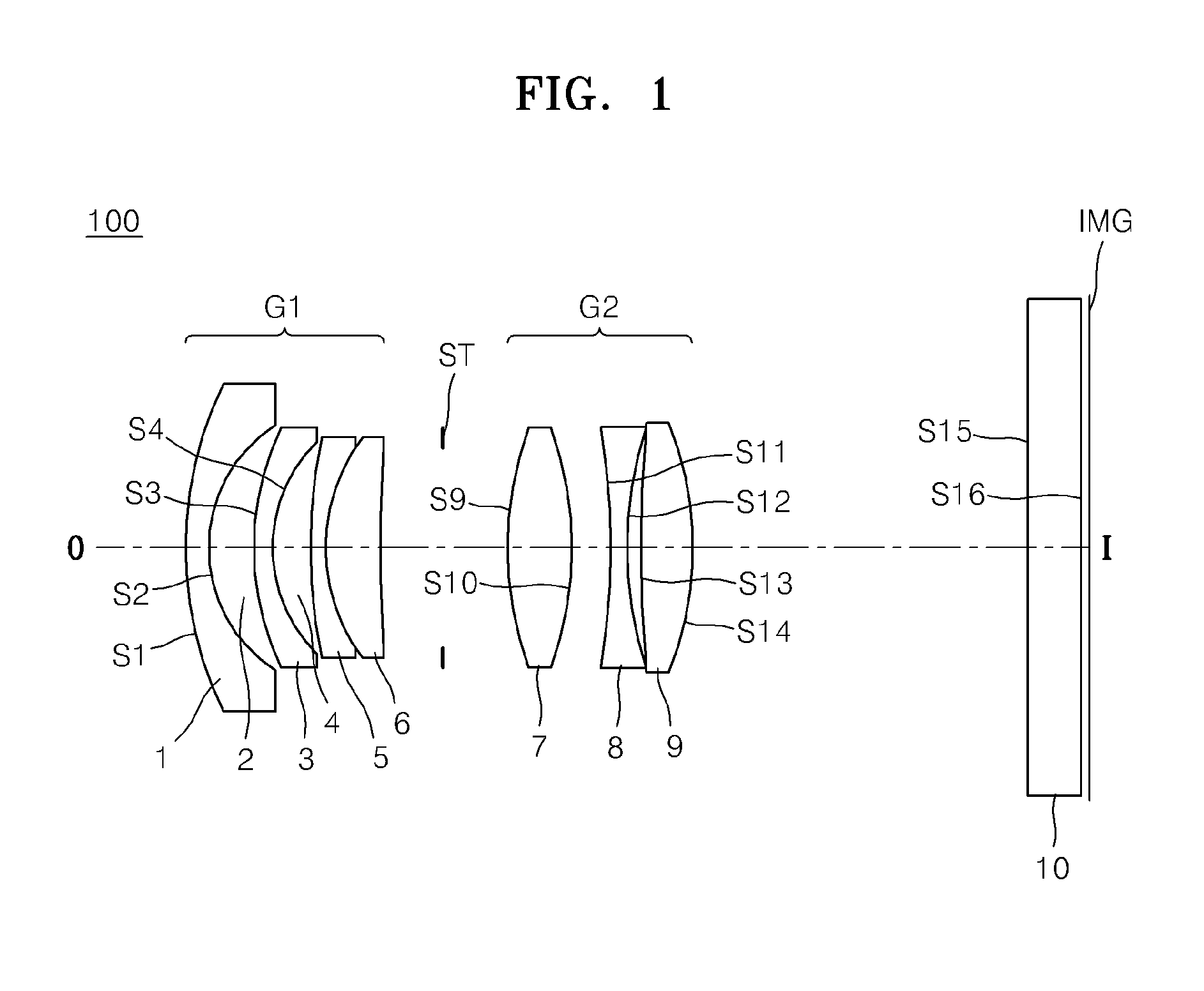
[0105]FIG. 1 illustrates a single focus lens system 100, according to an embodiment of the invention, and Table 1 below shows design data according to Embodiment 1. While lens surfaces of each lens are denoted with reference numerals in FIG. 1, the reference numerals of lens surfaces in other examples are omitted.

[0106]F: 16.13 mm Fno: 2.07 2w: 88.34

TABLE 1RefractiveAbbeLens surfaceCurvature radiusThicknessindex (Nd)number (Vd)S121.6451.201.4970081.6S28.3672.60S314.7781.101.5605968.8S4*8.5322.08ASPK: −2.00a: 3.33e−004b: 8.17e−008c: −1.10e−008d: 0.00e+000S529.1841.001.6463931.2S610.8502.891.8367737.7S749.9603.59STInfinity3.66S921.9133.601.7550052.3S10−21.6742.22S11−38.5120.901.8439923.8S1223.0510.77S1367.2032.901.7569252.0S14*−17.35719.05ASPK: −1.08a: 4.83e−005b: −6.21e−008c: 1.03e−008d: 0.00e+000S15Infinity2.921.5168064.2S16Infinity0.51IMG

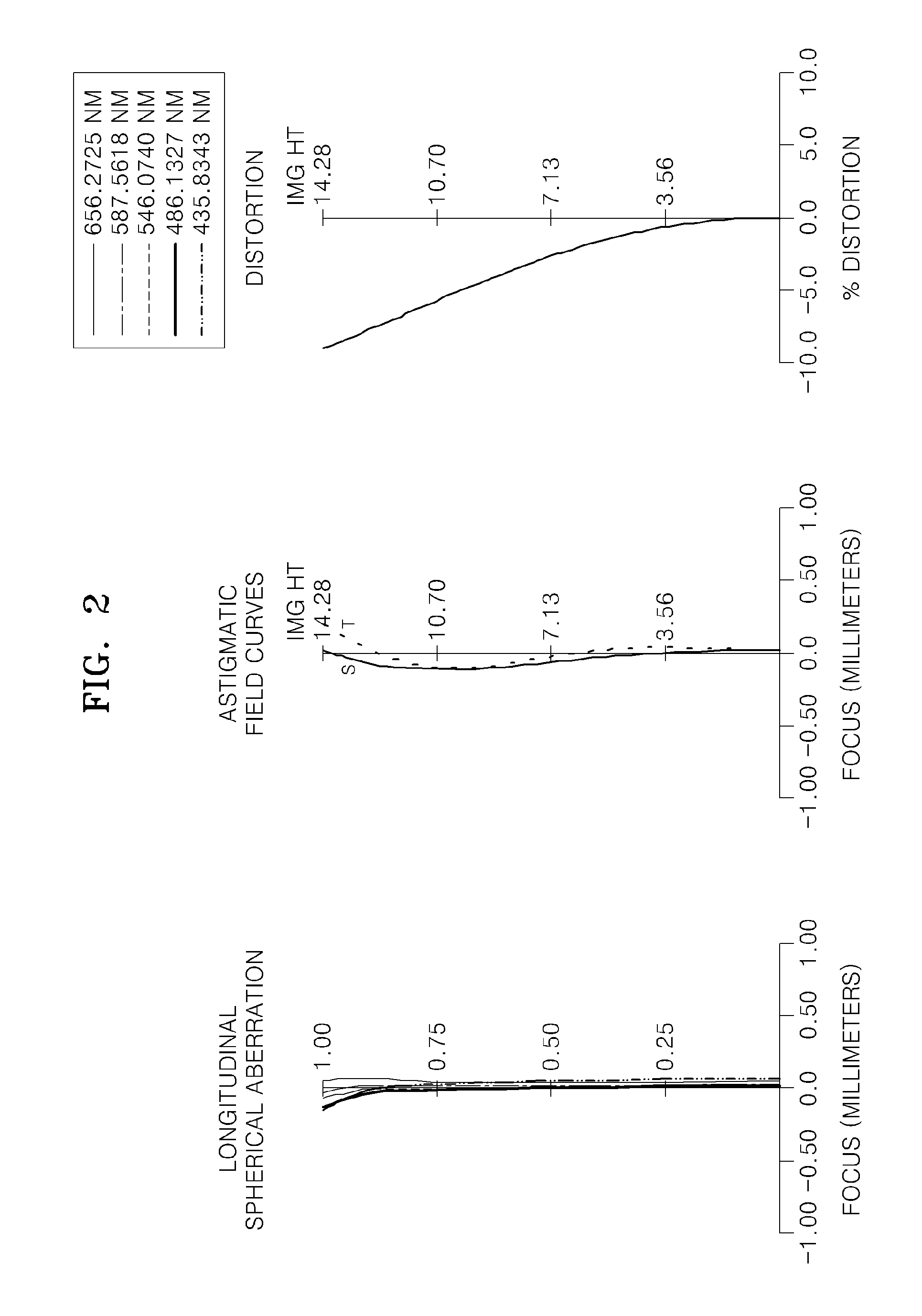
[0107]FIG. 2 is a diagram showing longitudinal spherical aberration, astigmatic field curves, and distortion of the single focus lens ...

Example

Embodiment 2

[0108]FIG. 4 illustrates a single focus lens system, according to another embodiment of the invention, and Table 2 below shows design data according to Embodiment 2.

[0109]F: 16.11 mm Fno: 2.08 2w: 89.05

TABLE 2RefractiveAbbeLens surfaceCurvature radiusThicknessindex (Nd)number (Vd)S121.6641.201.6023063.4S28.4582.55S3*16.5961.001.6075762.9ASPK: −2.00a: 3.23e−005b: 4.90e−007c: −9.54e−009d: 1.59e−010S410.6134.63S537.0262.741.9036631.3S6−57.5510.10S714.1001.001.8458923.8S810.5523.41STInfinity1.60S1024.6584.301.7555252.2S11*−12.8681.22ASPK: −0.59a: 7.74e−005b: −5.10e−007c: 1.96e−009d: 2.55e−012S12−23.7790.701.7819126.7S1318.0492.01S14−292.3903.241.6220361.4S15−12.88819.92S16Infinity2.921.5168064.2S17Infinity0.50IMG

[0110]FIGS. 5 and 6 are diagrams showing longitudinal and horizontal aberrations of the single focus lens system of FIG. 4, respectively.

Example

Embodiment 3

[0111]FIG. 7 illustrates a single focus lens system according to another embodiment of the invention, and Table 3 below shows design data according to Embodiment 3.

[0112]F: 16.12 mm Fno: 2.47 2w: 88.36

TABLE 3RefractiveAbbeLens surfaceCurvature radiusThicknessindex (Nd)number (Vd)S119.9401.301.4874970.4S28.3842.63S315.2541.201.5831359.0S4*8.0782.14ASPK: −1.00a: 1.73e−004b: 1.35e−006c: −9.33e−009d: 0.00e+000S530.4861.201.6476933.8S611.3912.751.8340037.3S782.8683.62STInfinity3.76S927.3293.101.7550052.3S10−18.1092.34S11−29.0510.901.8466623.8S1229.0510.67S13102.3942.841.7550151.2S14*−16.78319.12ASPK: −1.00a: 4.47e−005b: 1.57e−007c: 5.89e−009d: 0.00e+000S15Infinity2.921.5168064.2S16Infinity0.52IMG

[0113]FIGS. 8 and 9 are diagrams showing longitudinal and horizontal aberrations of the single focus lens system of FIG. 7, respectively.


PUM


Abstract

A single focus lens system and a photographing apparatus including the single focus lens system are disclosed. A single focus lens system is provided that includes a first lens group having a negative refractive power, a stop, and a second lens group having a positive refractive power, sequentially arranged in order from an object side, wherein the first lens group comprises first and second air lenses having a negative refractive power, a meniscus shape and a convex surface toward the object side, and the second lens group comprises a lens that has a positive refractive power, is disposed closest to the object side, and has a convex surface toward the object side.

Description

CROSS-REFERENCE TO RELATED PATENT APPLICATION[0001]This application claims the priority benefit of Korean Patent Application No. 10-2011-0089254, filed on Sep. 2, 2011, in the Korean Intellectual Property Office, which is incorporated herein in its entirety by reference.BACKGROUND[0002]1. Field of the Invention[0003]The invention relates to a single focus lens system and a photographing apparatus including the single focus lens system.[0004]2. Description of the Related Art[0005]Recently, the use of digital cameras and video cameras including a solid state pickup device such as a charge coupled device (CCD) or a complementary metal-oxide semiconductor (CMOS) has considerably increased. In particular, demand for lens interchangeable single reflex cameras is increasing, and common single reflex cameras have been distributed. Digital cameras including an image pickup device such as a CCD or a CMOS, or imaging optical devices such as cameras for use in mobile phones should be manufactur...

Claims


Application Information

Patent Timeline
IPC IPC(8): G02B13/04
CPCG02B13/04G02B9/10G02B13/18
Inventor LEE, TAE-KUN
Owner SAMSUNG ELECTRONICS CO LTD
Why Eureka
Try Eureka