Connection device

a technology of connection device and connection connection, which is applied in the direction of logic circuit coupling/interface arrangement, pulse technique, instruments, etc., can solve the problems of large inrush current and tripling of protective measures within the power supply, and achieve low drain to source resistance, less performance, and less damage.

Active Publication Date: 2013-04-11
ANALOG DEVICES INC
View PDF0 Cites 26 Cited by
  • Summary
  • Abstract
  • Description
  • Claims
  • Application Information

AI Technical Summary

Benefits of technology

[0010]Preferably the semiconductor devices are field effect transistors. Advantageously the field effect transistors are chosen for their switching performance. Such transistors exhibit a very low drain to source resistance when driven with an appropriate gate voltage. However such devices tend to perform less well during the transition from being fully off to fully on, and they are more susceptible to dissipation related damage than more general purpose field effect transistors.
[0011]Advantageously the field effect transistors have a drain to source on resistance of less than 5 mΩ when fully “on”, such an “on” state possibly including being driven with an enhanced gate voltage.

Problems solved by technology

This can give rise to large inrush currents as capacitive components of the load charge up.
Such inrush currents can perturb the operation of the power supply, possibly causing protective measures within the power supply to trip.
Furthermore the inrush currents may introduce perturbations in the power supplied to other loads connected to the power supply, and these perturbations may effect the operation of those circuits.
Furthermore, if the newly introduced load is faulty, its fault may also effect the operation of the power supply and the other loads or circuits connected to the supply.

Method used


Image

  • Connection device
  • Connection device
  • Connection device

Examples


Embodiment Construction

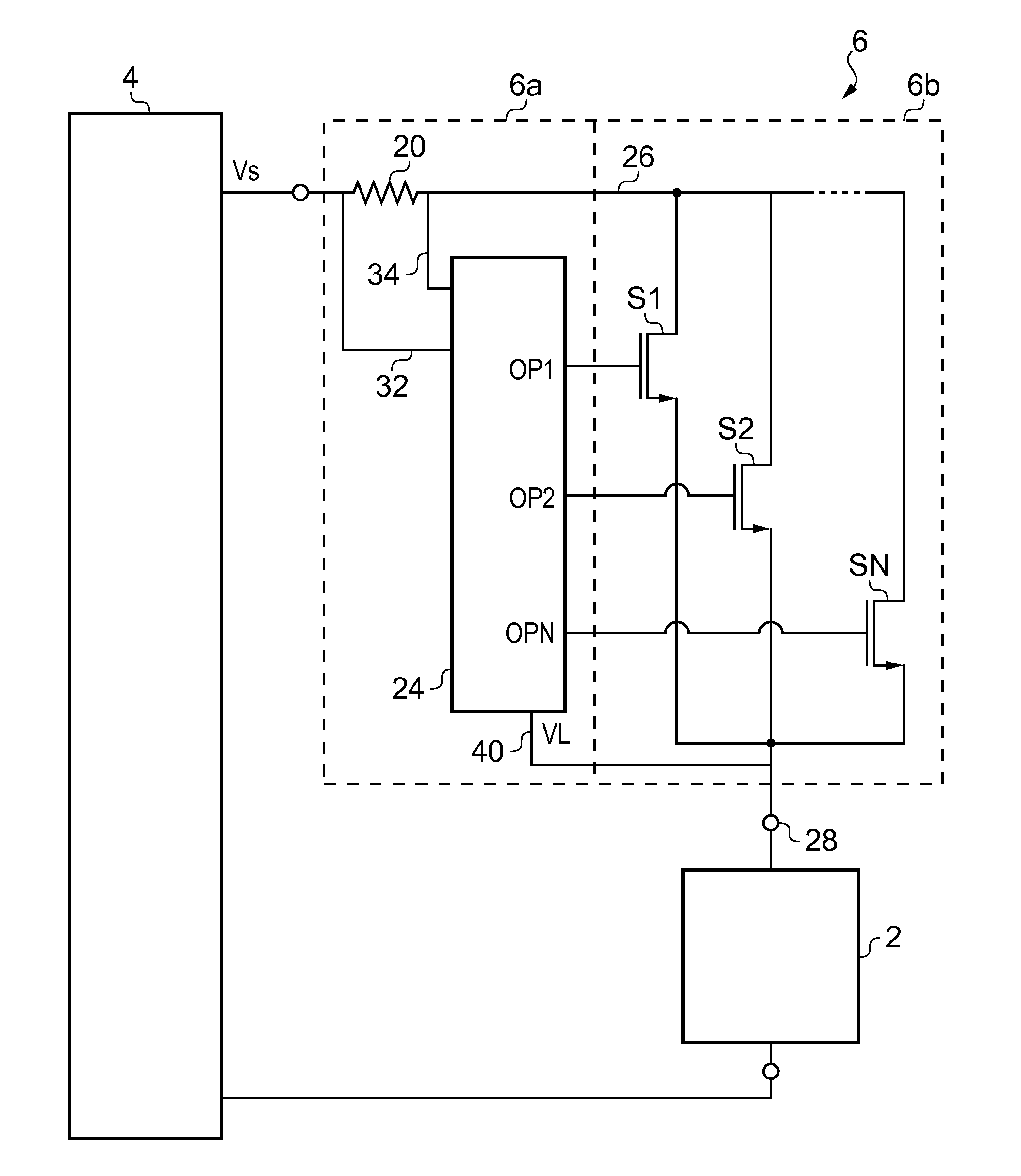
[0026]FIG. 1 illustrates a prior art hot swap circuit for enabling a load 2 to be connected to a power supply 4. It is to be assumed that the power supply may also be supplying other components which have been omitted for simplicity. The hot swap circuit is generally designated 6 and in this arrangement is physically associated with the load 2. The combination of the load 2 and hot swap circuits 6 can be electrically connected to or disconnected from the power supply by making or breaking connections between plug components 10 and 12 and respective sockets 14 and 16 which are connected to the power supply 4.

[0027]A current sensing resistor 20 and an electrically controllable current flow device 22 are provided in series between the plug and the load 2. The electrical current flow device 22 is, in this instance, a N-type field effect transistor. A controller 24 has first and second inputs connected to either side of the current sensing resistor 20 and an output connected to the gate ...


PUM


Abstract

A connection device for connecting a load to a power supply, comprising at least first and second current control devices arranged in parallel between the power supply and the load, and a controller arranged to switch the current control devices on in sequence for temporally overlapping on periods.

Description

FIELD OF THE INVENTION[0001]The present invention relates to a connection device for enabling power to be supplied to an electrical load.BACKGROUND OF THE INVENTION[0002]There are instances when it is desired to connect an electrical load to a power supply that is already on. This can give rise to large inrush currents as capacitive components of the load charge up. Such capacitive components may be real or parasitic components.[0003]Such inrush currents can perturb the operation of the power supply, possibly causing protective measures within the power supply to trip. Furthermore the inrush currents may introduce perturbations in the power supplied to other loads connected to the power supply, and these perturbations may effect the operation of those circuits. Furthermore, if the newly introduced load is faulty, its fault may also effect the operation of the power supply and the other loads or circuits connected to the supply.[0004]In order to address these issues it is known to pr...

Claims


Application Information

Patent Timeline
Patent Type & Authority Applications(United States)
IPC IPC(8): H03K17/296
CPCG05F1/575G05F1/468H03K3/012H03K17/0822H03K17/122H03K17/687H03K19/00315H03K19/017509
Inventor SPALDING, JR., GEORGE REDFIELDO'SULLIVAN, MARCUS
Owner ANALOG DEVICES INC
Why Eureka
Try Eureka