
Circuit arrangement for inductively operating sensor and method for the operation thereof

a technology of inductive operation and sensor, which is applied in the direction of instruments, lighting and heating apparatus, and domestic stoves or ranges, etc., can solve the problems of less widespread use no longer guaranteed clear and safe saucepan detection, and relatively complicated control of such sd sensors, etc., to reduce or even completely avoid overcoupling between leads to different sensors, improve the operation of such sensors, and reduce the resistance of drain sour

Inactive Publication Date: 2004-09-23
E G O ELEKTRO GERAETEBAU GMBH
View PDF20 Cites 1 Cited by
  • Summary
  • Abstract
  • Description
  • Claims
  • Application Information

AI Technical Summary

Benefits of technology

[0007] Within the framework of the invention it has been shown that through the use of a MOSFET with such a low drain-source resistance, it is possible to reduce or even completely avoid overcoupling between leads to different sensors. This greatly improves the operation of such sensors, for example in SD systems. Here a high detection reliability is required, because otherwise when no saucepan is placed on a cooking point, the latter does not operate and this is unacceptable to the user. In addition, after removing a saucepan from a cooking point this must be detected and said point switched off, because otherwise operation is continued under no-load conditions. This wastes energy and gives rise to an accident risk. In addition, an EMC test can be better handled by a switching means or MOSFET according to the invention.
[0008] According to a further development of the invention, for each sensor there is precisely one switching means, which improves the controllability of the individual sensors.
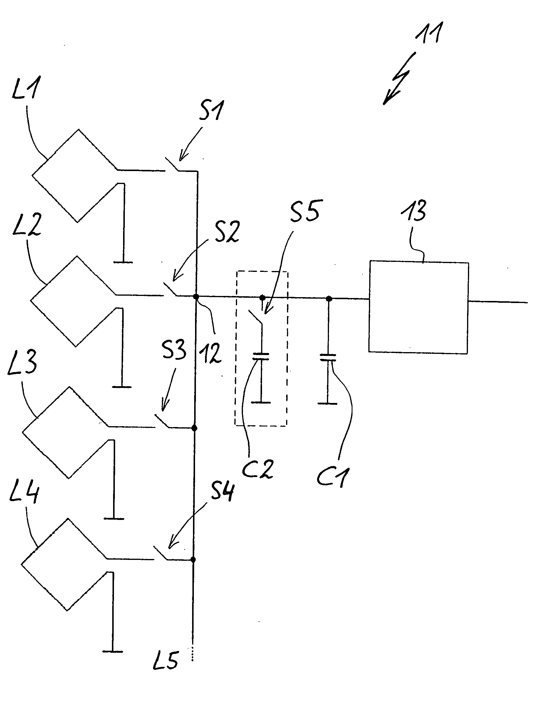
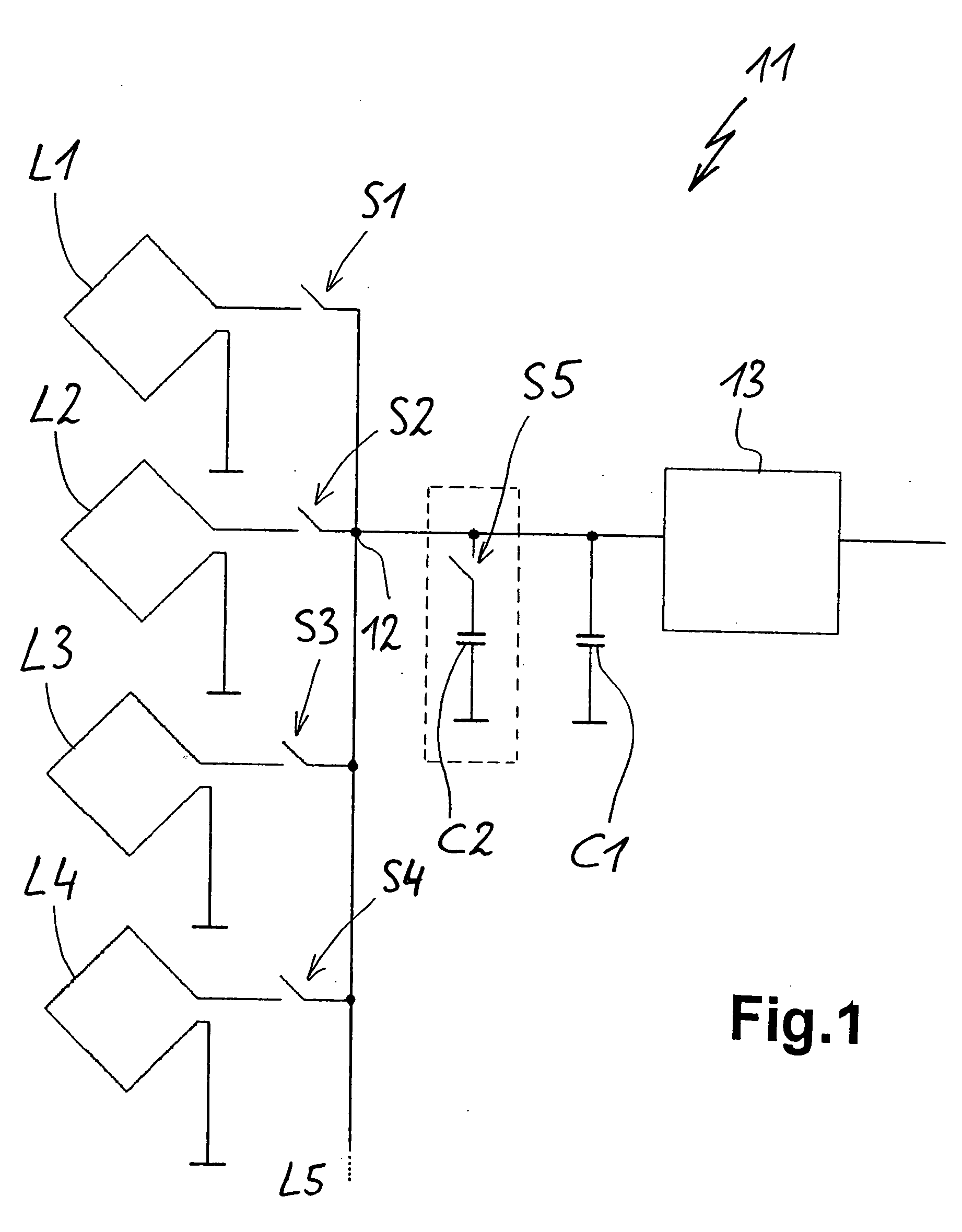
[0010] In a further development of the invention a second resonant circuit capacitor is connected parallel to the first resonant circuit capacitor. This makes it possible to produce a second measuring frequency. This makes it possible to better detect and avoid HF interference which can be prejudicial to saucepan detection. This is particularly the case if the HF interference does not have a constant, but instead a varying frequency and possibly both or all the measuring frequencies interfere at different times. Thus, it is always possible to very reliably detect the presence of a saucepan. There must be a certain difference between the different measuring frequencies, for example between approximately 5 and 10%.
[0012] In the case of a method according to the invention for the operation of the aforementioned circuit arrangement having the features of claim 6, the gate control voltage at the MOSFET can be readjusted. It is therefore possible to produce a frequency which is constant over varying temperatures. It is consequently possible to prevent varying ambient temperatures, for example also through the operation of heating devices of a cooking zone.

Problems solved by technology

Also in the afore-mentioned prior art, the control of such SD sensors is relatively complicated, which has prevented a more widespread use of such SD sensors for example in cooking zones.
If the resonant circuit frequency is displaced by roughly this range through overcoupling, a clear and safe saucepan detection is no longer ensured.
Here a high detection reliability is required, because otherwise when no saucepan is placed on a cooking point, the latter does not operate and this is unacceptable to the user.
This wastes energy and gives rise to an accident risk.

Method used


Image

  • Circuit arrangement for inductively operating sensor and method for the operation thereof
  • Circuit arrangement for inductively operating sensor and method for the operation thereof

Examples


Embodiment Construction

[0017] FIG. 1 shows a circuit arrangement 11, such as can for example be used for a SD system and which has four coils L1 to L4, but more can be provided. The coils L operate as SD sensors, as stated hereinbefore.

[0018] In each case the coils L1 to L4 are connected by means of a switch S1 to S4 to a common circuit node or junction 12, which is connected to a basic oscillator circuit 13 for producing the resonant circuit frequency. There is also a resonant circuit capacitor C1, which in each case together with a coil L forms a parallel resonant circuit of the inductance of the coil and the resonant circuit capacitance. In this way and in the manner of a multiplex operation, in each case one coil is connected by the corresponding switch S to the circuit junction 12. The other switches S are open and the corresponding coils L separated. The basic oscillator circuit 13 then emits a signal for a further evaluation of the resonant circuit frequency to establish whether it has changed in s...


PUM


Abstract

In the case of a circuit for several inductive pot or saucepan detection coils a control and evaluation circuit is provided. Using switches in the form of MOSFETs, the control or evaluating circuit is in each case connected to one coil in multiplex operation. The MOSFETs have a low drain-source resistance in order to avoid off-resonancing of resonant circuit frequencies due to the overcoupling of several leads to the coils.

Description

FIELD OF APPLICATION AND PRIOR ART[0001] The invention relates to a circuit arrangement for several inductively operating sensors, as well as to a method for the operation thereof.[0002] Pot or saucepan detection systems are known which use inductively operating sensors or so-called PD / SD sensors. Such SD sensors together with the control means are described in EP 442 275 A1 and EP 469189 A1. Also in the afore-mentioned prior art, the control of such SD sensors is relatively complicated, which has prevented a more widespread use of such SD sensors for example in cooking zones.[0003] In many cases the frequency change in a SD system on setting down a saucepan is approximately 3 to 5%. If the resonant circuit frequency is displaced by roughly this range through overcoupling, a clear and safe saucepan detection is no longer ensured.[0004] It is an object of the invention to provide a circuit arrangement of the afore-mentioned type and a method for the operation thereof, which are able ...

Claims


Application Information

Patent Timeline
Patent Type & Authority Applications(United States)
IPC IPC(8): F24C7/04G01D5/20G01B7/00H05B6/12
CPCG01D5/202G01D5/2013
Inventor KNAPPE, GERDPERRIN, WILHELM
Owner E G O ELEKTRO GERAETEBAU GMBH
Learn More