Continuously variable transmission and a working machine including a continuously variable transmission

Active Publication Date: 2013-05-16
VOLVO CONSTR EQUIP
View PDF8 Cites 20 Cited by
  • Summary
  • Abstract
  • Description
  • Claims
  • Application Information

AI Technical Summary

Benefits of technology

[0036]The configuration of the continuously variable transmission allows the variator unit to be controlled by a dual yoke enabling simultaneous control of displacements of the first and second hydraulic machines via a single actuator. The continuously variable t

Problems solved by technology

A problem with U.S. Pat. No. 5,980,410 is that the configuration of the continuously variable transmission will require presence of gear stages with a substantial gear ratio in order to enable the bands of input to o

Method used


Image

  • Continuously variable transmission and a working machine including a continuously variable transmission
  • Continuously variable transmission and a working machine including a continuously variable transmission
  • Continuously variable transmission and a working machine including a continuously variable transmission

Examples


Embodiment Construction

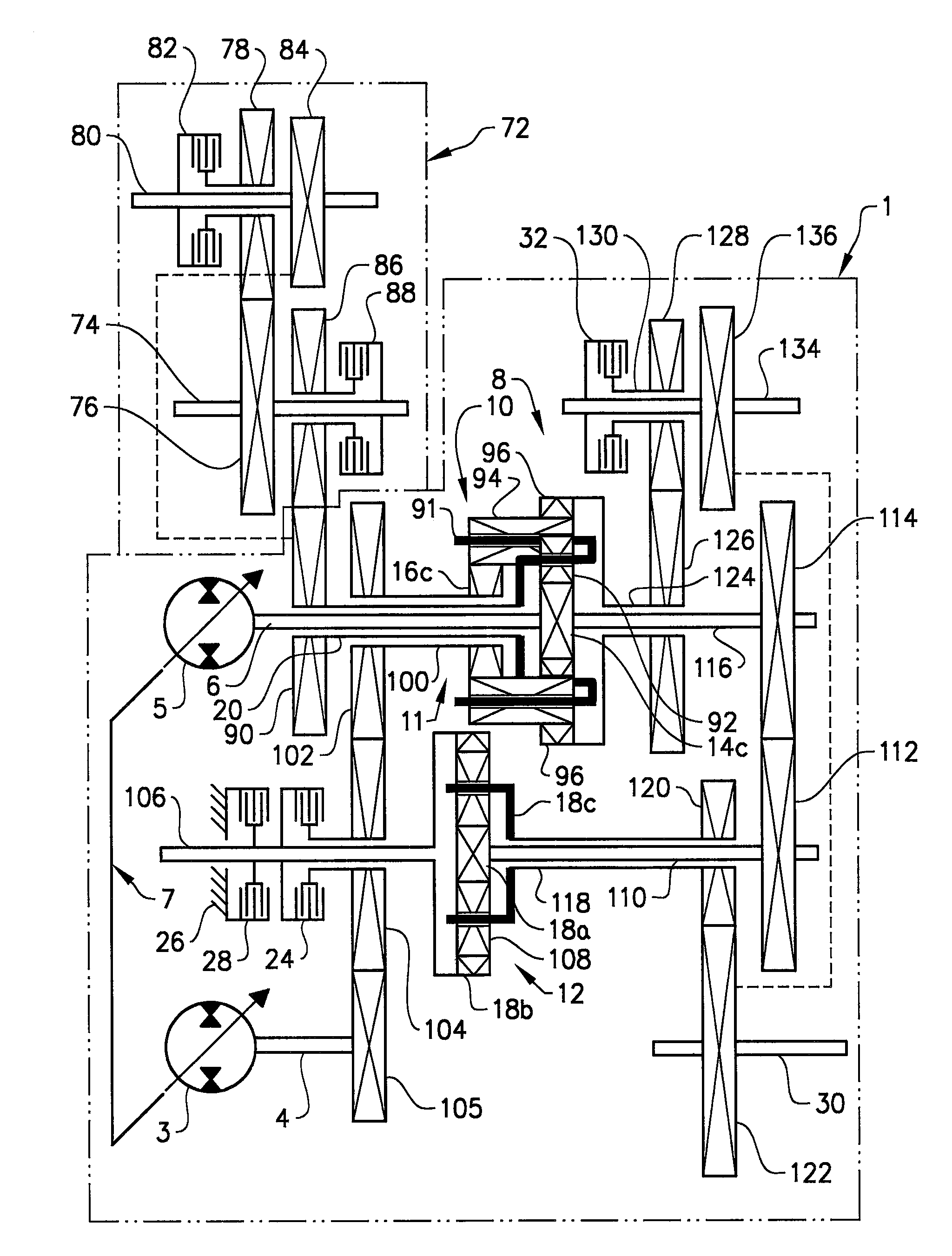
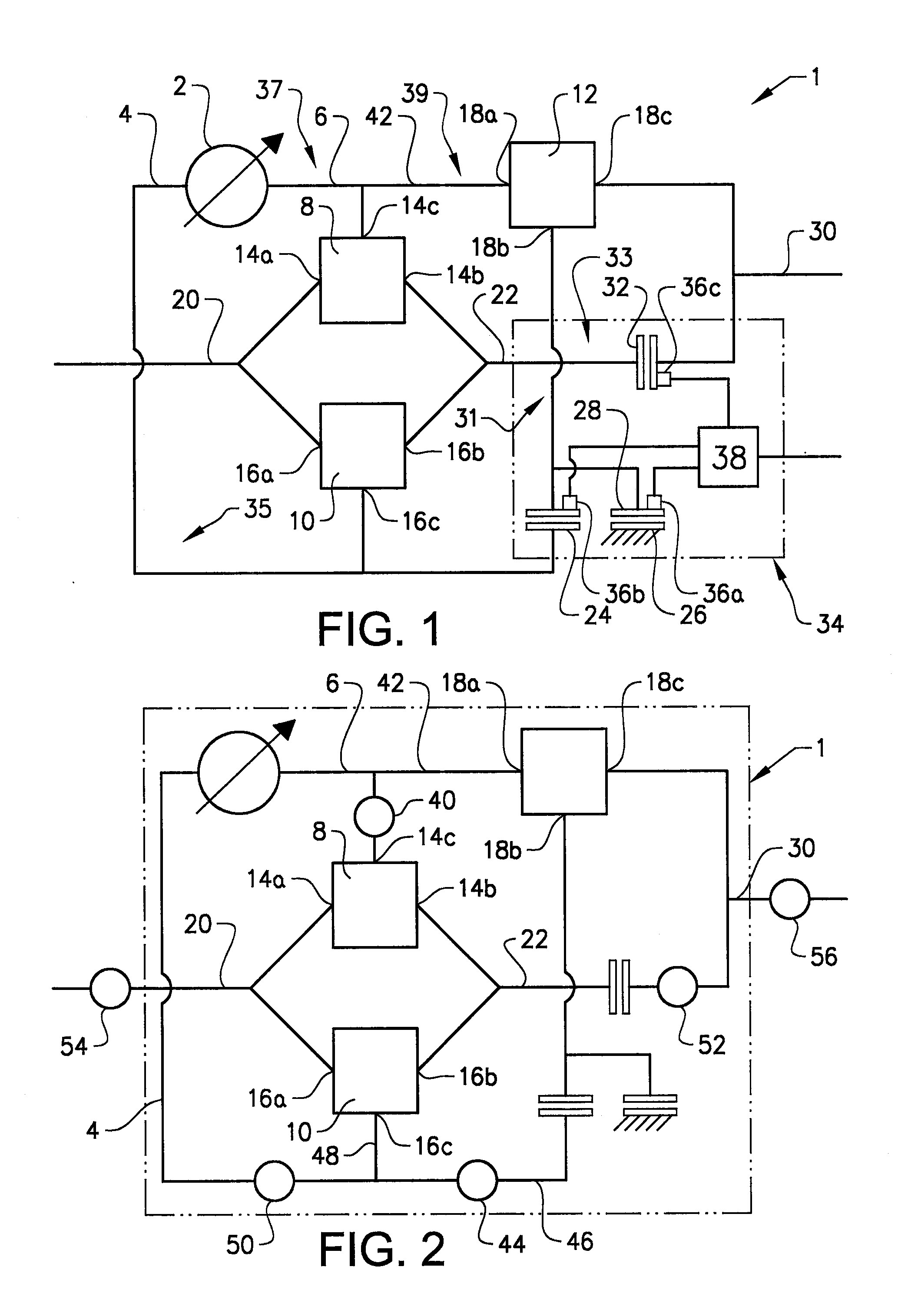
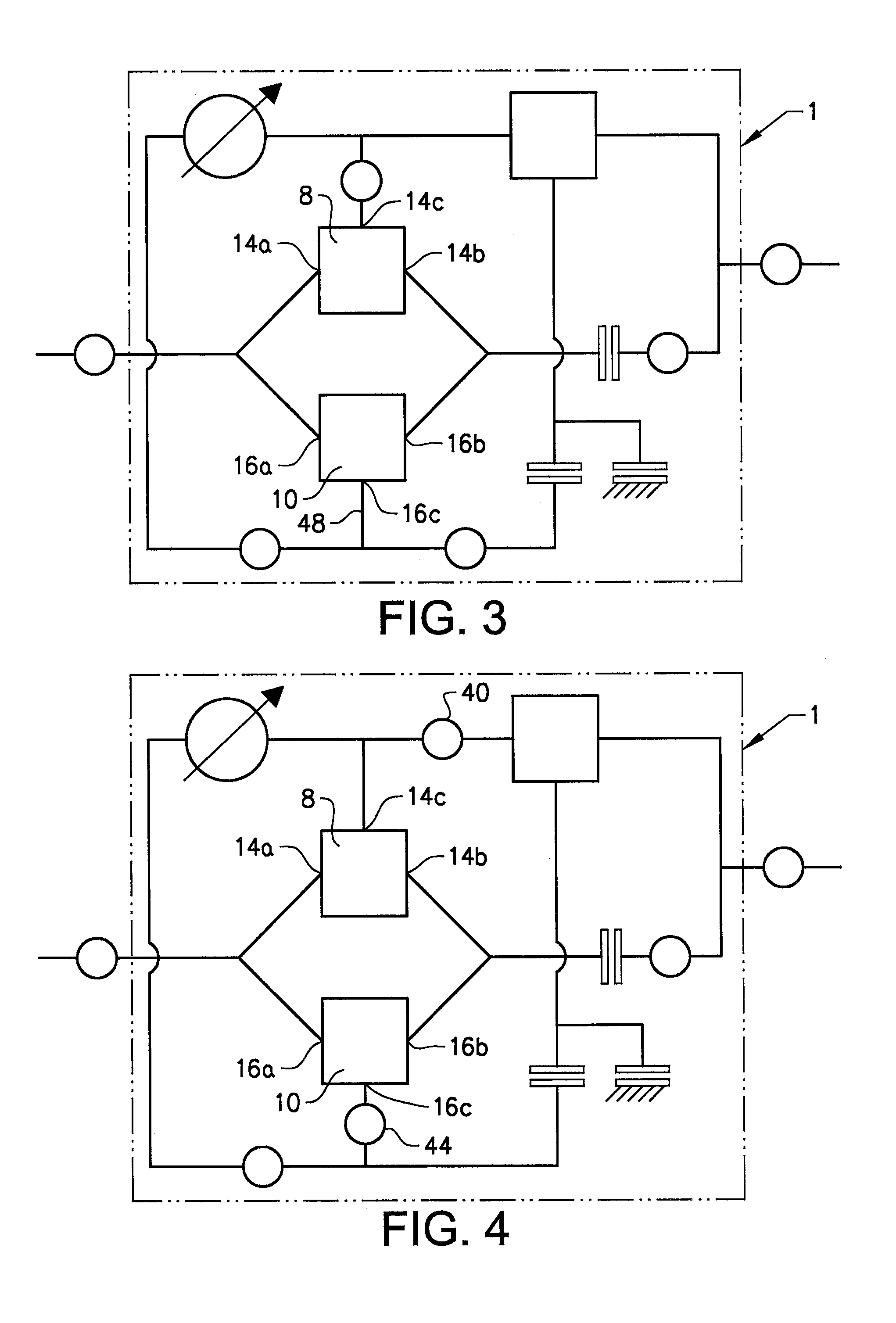
[0060]In FIG. 1 a schematic illustration of the design of a continuously variable transmission 1 according to the invention is shown. The continuously variable transmission 1 includes a variator unit 2 having a variator input shaft 4 and a variator output shaft 6. The variator unit may be of a hydraulic type including a first hydraulic machine provided with the input shat of the variator unit and a second hydraulic machine provided with the output shaft of the variator unit, the first and second hydraulic machines being hydraulically connected to each other, or of an electric type including a first electric machine provided with said input shaft of the variator unit and a second electric machine provided with the output shaft of the variator unit, the first and second electric machines being electrically connected to each other. Preferably the variator is of the hydraulic type. In one embodiment the variator unit may be a hydrostatic transmission having two bent axis- or swash plate...


PUM


Abstract

A continuously variable transmission includes a variator unit having a variator input shaft and a variator output shaft, and first, second and third planetary gear sets. The first and second planetary gear sets are arranged together and each includes a first member operatively connected to a common transmission input shaft and a second member operatively connected to a common output shaft, each of the first and second planetary gear sets further including a third member. The third planetary gear set has a first, second and third member. The variator input shaft is operatively connected to the third member of the second planetary gear set and the variator output shaft is operatively connected to the third member of the first planetary gear set. The first member of the third planetary gear set is operatively connected to the variator output shaft. The second member of the third planetary gear set is selectively connectable to the third member of the second planetary gear set and selectively connectable to the transmission housing. The third member of the third planetary gear set is operatively connected to a transmission output shaft. The common output shaft is selectively connectable to the transmission output shaft.

Description

BACKGROUND AND SUMMARY[0001]The invention relates to a continuously variable transmission and a working machine comprising such a continuously variable transmission.[0002]The invention is applicable on working machines within the fields of industrial construction machines, in particular wheel loaders and articulated haulers. Although the invention will be described hereinafter with respect to a wheel loader, the invention is not restricted to this particular machine, but may also be used in other heavy working machines, such as dump trucks, graders, excavators or other construction equipment.[0003]A continuously variable transmission is a transmission which speed ratio can be continuously varied over a designed range. Continuously variable transmissions are useful due to enabling operation of a prime mover at optimum speed or at optimum fuel economy while still providing a desired rotational speed at the output shaft of the transmission. In a continuously variable transmission a spe...

Claims


Application Information

Patent Timeline
IPC IPC(8): F16H3/62
CPCE02F9/202E02F9/2079E02F9/2253E02F9/2289E02F9/2296F16H2037/103F16H2200/202F16H47/04F16H2037/102F16H2200/201F16H2037/101F16H2200/2023F16H3/62
Inventor MATTSSON, PERKERBLOM, MATS
Owner VOLVO CONSTR EQUIP
Why Eureka
Try Eureka