Pneumatic tire

a pneumatic tire and tire body technology, applied in the field of pneumatic tires, can solve the problems of reducing the rigidity of the tread portion to generate a difference in rigidity, and it is difficult to ensure both drivability and partial wear resistance at the same time, so as to suppress the reduction in rigidity, shorten the length, and improve the pneumatic tire in partial wear resistance

Inactive Publication Date: 2013-07-25
BRIDGESTONE CORP
View PDF5 Cites 4 Cited by
  • Summary
  • Abstract
  • Description
  • Claims
  • Application Information

AI Technical Summary

Benefits of technology

[0009]Here, the “compound groove partitioned into a first groove portion and a second groove portion by a first groove side and a second groove side” in the present invention may include, without impairing the effect of the invention, a compound groove partitioned into the first groove portion and the second groove portion that are slightly spaced apart from each other due to manufacturing reasons. That is, the first groove side and the second groove side may not be technically connected at the intersection, whereas a virtual line connecting the disconnected first groove sides and a virtual line connecting the disconnected second groove sides still intersect with each other to form the intersection. Further, the “groove extending direction” refers to an extending direction, in plan view, of a line passing through the center of the compound groove width measured in a direction perpendicular to the oblique side portion and the extension thereof, and the “groove transverse direction” refers to a direction, in plan view, perpendicular to the oblique side portion and the extension thereof.
[0010]Here, in the pneumatic tire of the present invention, the oblique side portion is preferably shorter in length than the second groove side. The oblique side portion shorter in length than the second groove side allows the tapered surface to extend across the most part of the first groove portion and second groove portion, which further improves the pneumatic tire in partial wear resistance.
[0011]Further, in the pneumatic tire of the present invention, the tapered surface forms an angle with a plane perpendicular to the tread surface, the angle preferably falling within a range of 20° to 75° measured from the acute-angle side. The tapered surface needs to form an angle of at least 20° with a plane perpendicular to the tread surface in order to sufficiently suppressing reduction in rigidity in the vicinity of the oblique side portion to thereby improve partial wear resistance. On the other hand, the angle needs to be 75° at maximum in order to ensure drainage, and also to avoid unnecessarily increasing the groove area required for forming the tapered surface, to thereby suppress reduction in rigidity. It should be noted that, in the present invention, “the tapered surface forms an angle with a plane perpendicular to the tread surface”, which means that the tapered surface forms an angle with a virtual plane passing through the oblique side portion in a direction perpendicular to the tread surface.
[0012]In addition, in the pneumatic tire of the present invention, the oblique side portion forms an inclination angle relative to the tire circumferential line, the inclination angle preferably falling within a range of 15° to 85° measured from the acute-angle side. The inclination angle less than 15° may fail to ensure sufficient rigidity in the tire circumferential direction in the vicinity of the oblique side portion. On the other hand, the inclination angle over 85° may fail to ensure sufficient rigidity in the tire width direction in the vicinity of the oblique side portion.
[0013]Then, in the pneumatic tire of the present invention, the first groove portion and the second groove portion both preferably have a groove wall extending from the second groove side, the groove wall forming an angle with a plane perpendicular to the tread surface, which preferably varies in an extending direction of the second groove side. The angle of a groove wall extending from the second groove side may be adapted to change, so as to obtain a high partial wear resistance and excellent drivability, while providing excellent turning performance. It should be noted that, in the present invention, the “groove wall extending from the second groove side forms an angle with a plane perpendicular to the tread surface”, which means that the groove wall extending from the second groove side forms an angle with a virtual plane passing through the second groove side in a direction perpendicular to the tread surface. Further, the “virtual plane passing through the second groove side” refers to a virtual plane passing through a tangent of the second groove side when the second groove side is a curved line.
[0014]The present invention has an object to advantageously solve the aforementioned problems, and a pneumatic tire of the present invention has a feature of including, in a tread surface, a groove partitioned by at least three groove sides in plan view, in which the groove sides extending in a longitudinal direction of the groove have groove walls extending toward a groove bottom, one or more of the groove walls being formed as tapered surfaces at least in part thereof; and in which the tapered surfaces each form an angle with a plane perpendicular to the tread surface, which varies in an extending direction of the groove side.

Problems solved by technology

However, the grooves formed in a tread surface of the tread portion, which may improve the drivability or the like, also reduces the rigidity of the tread portion to generate a difference in rigidity.
As a result, a pneumatic tire for a motorcycle having a circumferential groove and a lateral groove formed in a tread surface of a tread portion for the purpose of ensuring drivability can be subjected to significant partial wear, and thus it has been difficult to ensure both drivability and partial wear resistance at the same time.

Method used


Image

  • Pneumatic tire
  • Pneumatic tire
  • Pneumatic tire

Examples


example 1

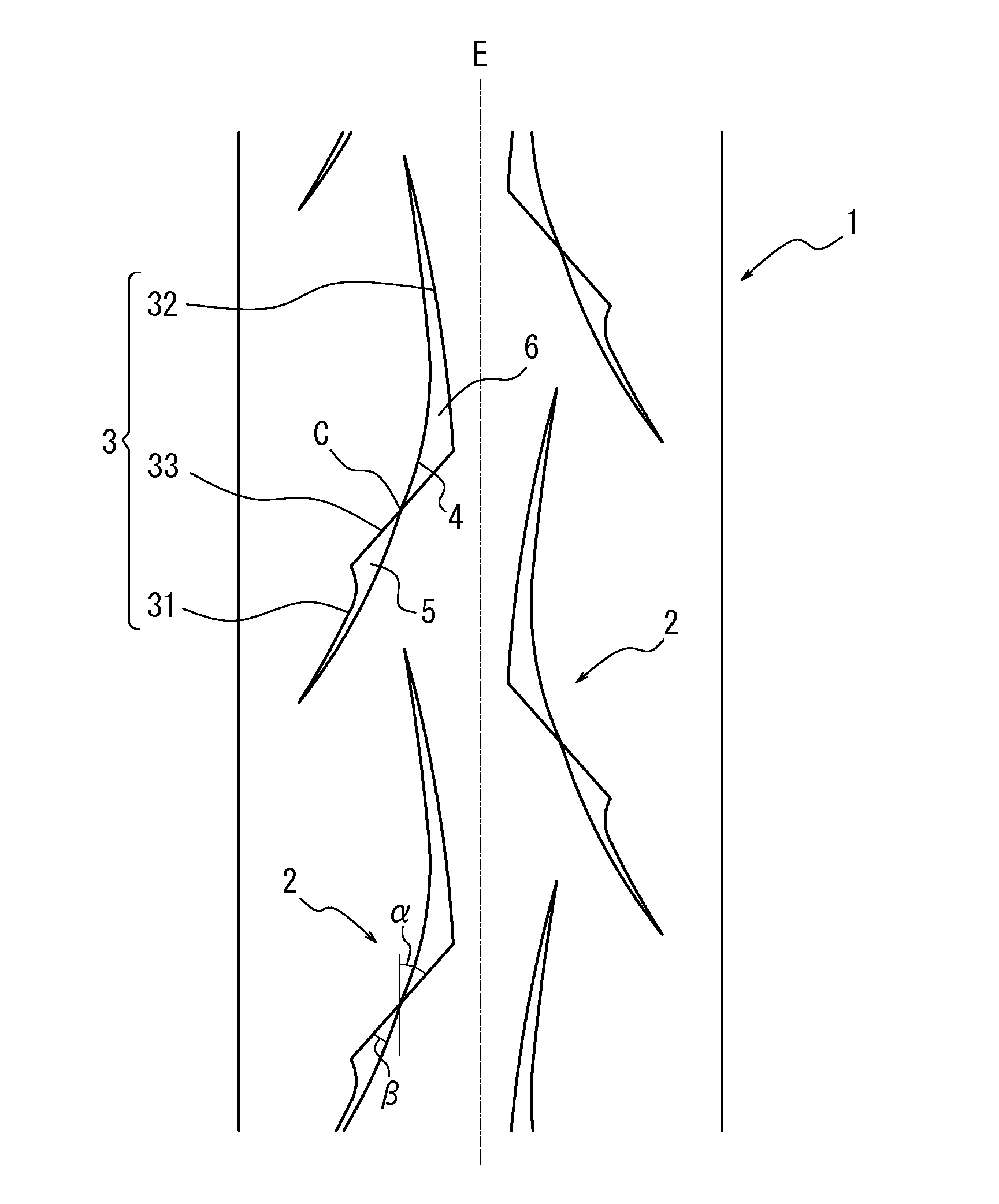
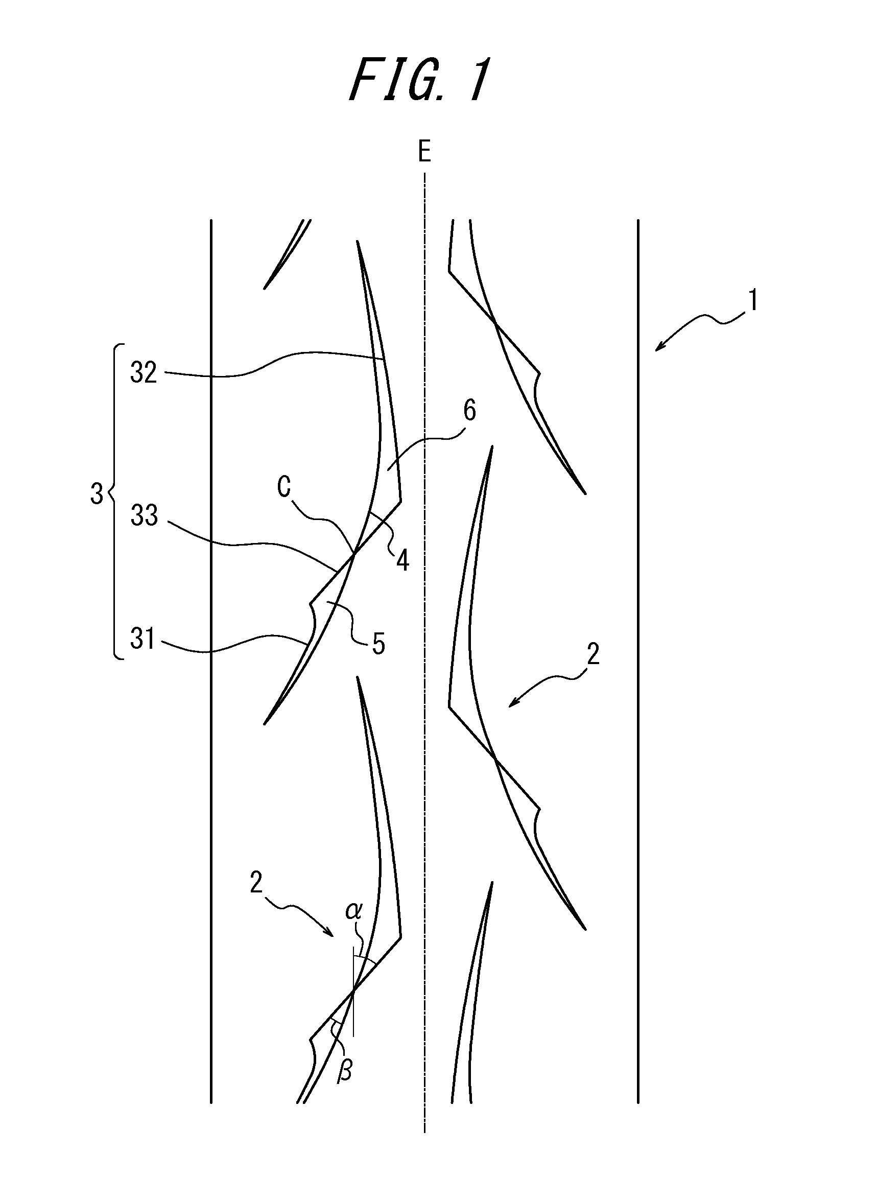
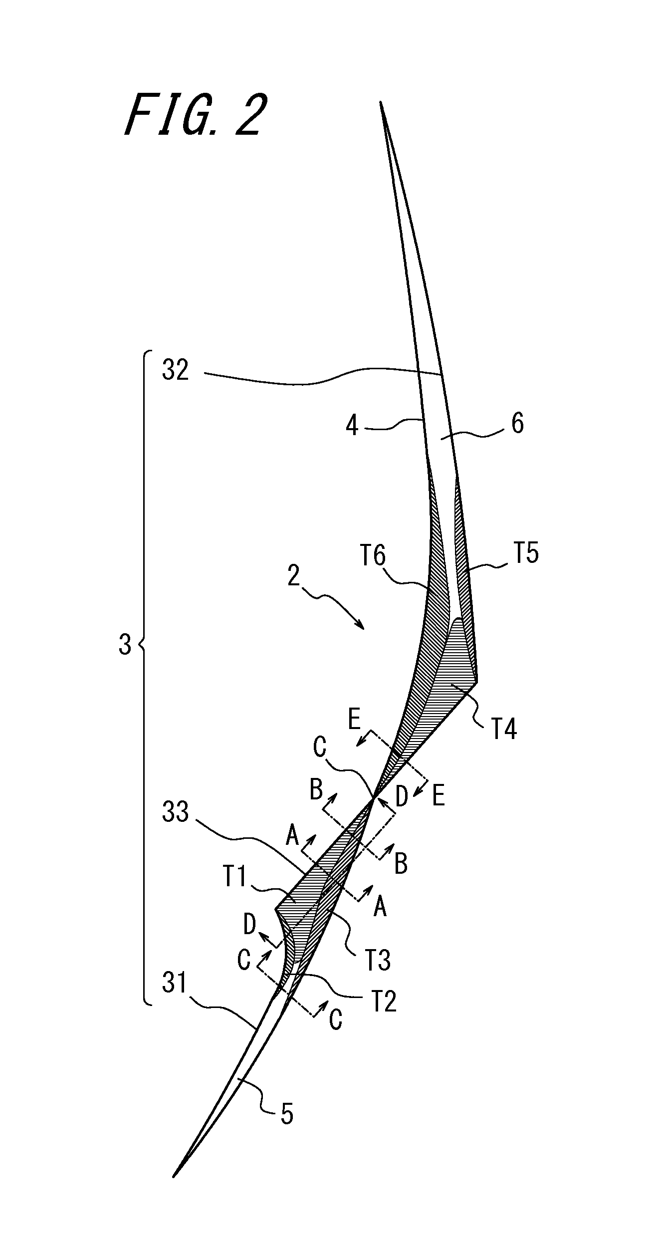
[0060]Pneumatic tires (for rear wheels) which were configured as illustrated in FIGS. 1 to 4 and had the specifications shown in Table 1 were manufactured as samples by a conventional method. The tires were each in size 180 / 55ZR17.

[0061]Then, the tires were subjected to performance evaluation according to the following methods. The evaluation results are shown in Table 1.

examples 2 to 5

[0063]Pneumatic tires each having a configuration similar to that of Example 1, except in that the specifications were changed as shown in Table 1, were manufactured as samples, which were subjected to performance evaluation similarly to Example 1. The evaluation results are shown in Table 1.

[0064]Drivability

[0065]The pneumatic tires thus manufactured were each mounted to a rim in size of MT5.50×17, which is assembled as a rear tire of a real vehicle of 600 cc displacement at a filling air pressure of 190 kPa. The vehicle was then repeatedly driven at 40 km / h to 250 km / h at a camber angle of 0° to 50° on a round track of 10 km, so as to evaluate drivability. Specifically, drivability was evaluated based on the feeling of a professional rider, which was indexed with a score of 100 representing the drivability of Comparative Example 1. A larger index value indicates that the tire is more excellent in drivability.

[0066]Partial Wear Resistance

[0067]The pneumatic tires thus manufactured ...


PUM


Abstract

The present invention has an object of providing a pneumatic tire having a tread pattern capable of providing both excellent drivability and a high partial wear resistance. The pneumatic tire of the present invention includes, in a tread surface, a compound groove partitioned into a first groove portion and a second groove portion by a first groove side and a second groove side, the first groove side having an oblique side portion diagonally disposed relative to a tire circumferential line in plan view, the second groove side intersecting with the oblique side portion of the first groove side at an acute angle in plan view, in which: the first groove portion and the second groove portion both have a groove depth that gradually reduces in an extending direction of the groove toward an intersection between the oblique side portion and the second groove side; and a groove wall extending from the first groove side is formed as a tapered surface mildly-sloped toward a groove bottom on the intersection side when viewed in the groove transverse direction. Further, the pneumatic tire of the present invention includes, in a tread surface, a groove partitioned by at least three groove sides in plan view, in which: one or more of groove walls extending from one of the at least three groove sides that extends in the longitudinal direction of the groove is formed as a tapered surface at least in part thereof; and the tapered surface forms an angle with a plane perpendicular to the tread surface, which varies in the extending direction of the groove side.

Description

TECHNICAL FIELD[0001]The present invention relates to a pneumatic tire, and more particularly to a pneumatic tire suitably used as a pneumatic tire for a motorcycle.BACKGROUND ART[0002]In general, a pneumatic tire, in particular, a pneumatic tire for a motorcycle is known to be largely affected, in terms of drivability, by the shape of grooves (tread pattern) formed in a tread surface of a tread portion.[0003]As an example of a conventional pneumatic tire for a motorcycle, there has been proposed a pneumatic tire for a motorcycle having a circumferential groove extending substantially in the tire circumferential direction and a plurality of lateral grooves extending substantially in the tire width direction, the grooves being formed in a tread surface of the tire (see, for example, Patent Literatures 1, 2). In the aforementioned pneumatic tire for a motorcycle, the circumferential groove functions to improve drivability and to prevent skidding while the lateral grooves exert drive f...

Claims


Application Information

Patent Timeline
Patent Type & Authority Applications(United States)
IPC IPC(8): B60C11/03
CPCB60C11/0302B60C11/13B60C2200/10B60C11/1323B60C11/1315B60C2011/0374B60C11/03B60C2011/0383B60C11/032
Inventor OSHIMA, MASATOMO
Owner BRIDGESTONE CORP
Why Eureka
Try Eureka