

Recordable optical disc, recording device, and recording method
a recording device and optical disc technology, applied in the direction of optical beam sources, digital signal error detection/correction, instruments, etc., can solve the problems of indefinite degree of influence on the other layers, inability to predict the effect of transmittance change, and difficulty in designing the opc areas in the respective recording layer and designing the areas, etc., to achieve the effect of minimizing the influence of transmittance chang
- Summary
- Abstract
- Description
- Claims
- Application Information
AI Technical Summary
Benefits of technology
Problems solved by technology
Method used
Image

Examples
Embodiment Construction
[0070]An embodiment of the present invention will be described below in the following order.
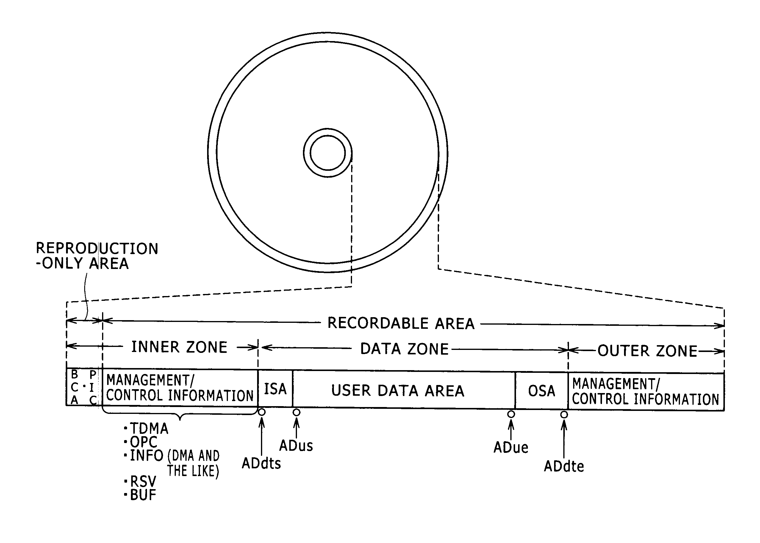
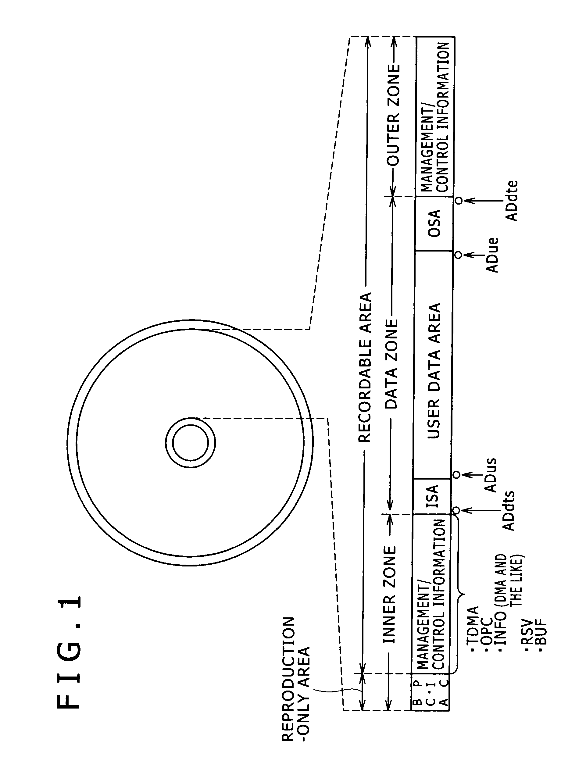
[1. Disk Structure]
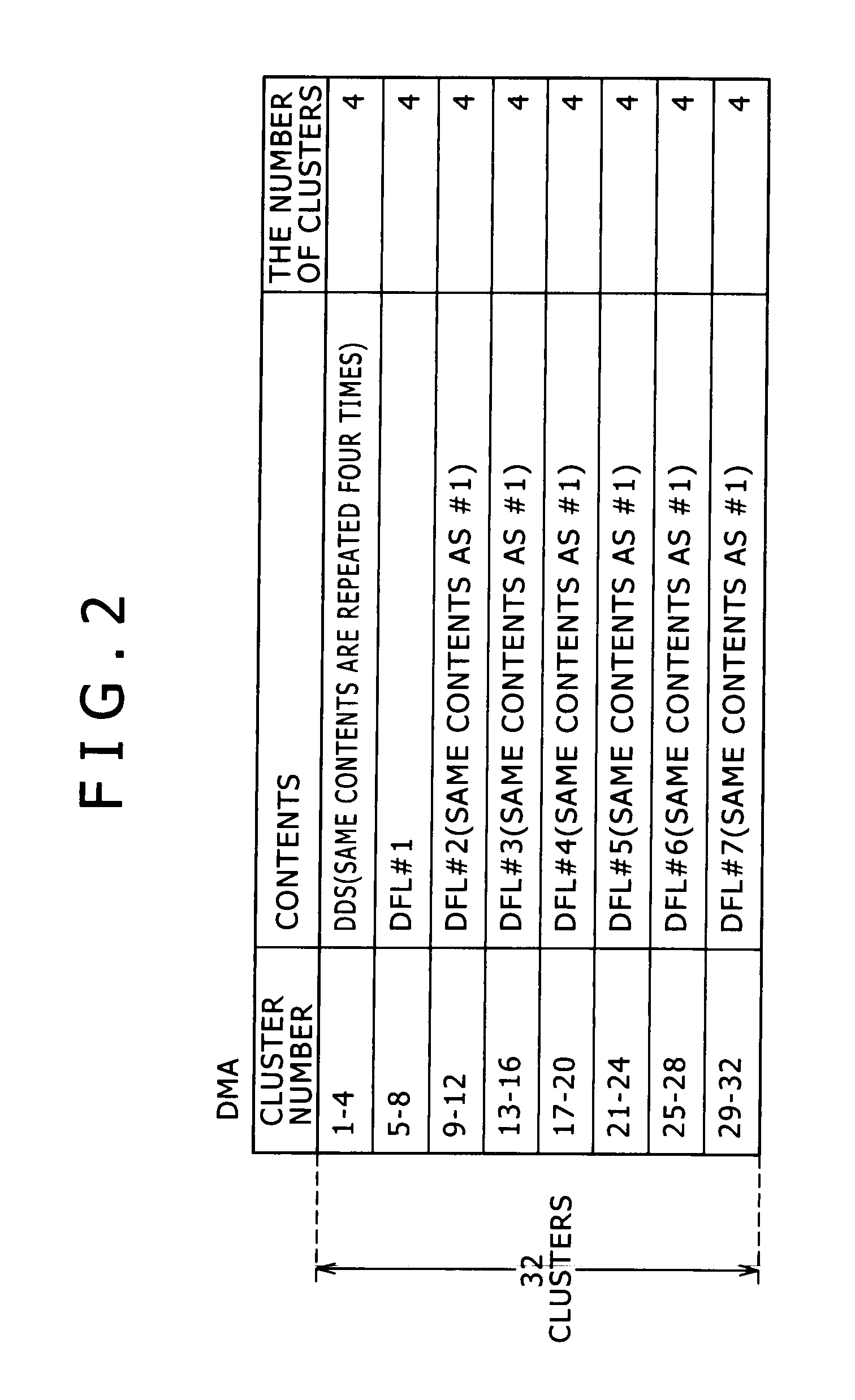
[2. DMA]
[3. TDMA]
[4. Plural-layer Disk / Inner Zone of Existing Double-layer Disk]
[5. Inner Zone of Newly-developed Triple-layer Disk]
[6. Inner Zone of Quadruple-layer Disk of Embodiment]
[7. Disk Drive Device]
[1. Disk Structure]
[0071]First, the outline of an optical disk of the embodiment will be described. This optical disk can be implemented as a write-once disk (BD-R) or a rewritable disk (BD-RE) in the category of a high-density optical disk system referred to as the so-called Blu-ray Disc.
[0072]One example of the physical parameters of the high-density optical disk of the present embodiment will be described.
[0073]As the disk size of the optical disk of the present example, the diameter is 120 mm and the disk thickness is 1.2 mm. That is, from these points, this optical disk is the same as a disk of the CD (Compact Disc) system and a disk of the DVD (Digital Versatile Di...
PUM
| Property | Measurement | Unit |
|---|---|---|
| radial width | aaaaa | aaaaa |
| radial width | aaaaa | aaaaa |
| gap distance | aaaaa | aaaaa |
Abstract
Description
Claims
Application Information