Portable Electromagnetic Interference Shield with Flexible Cavity

Inactive Publication Date: 2013-10-24
E C RYAN INT
View PDF4 Cites 23 Cited by
  • Summary
  • Abstract
  • Description
  • Claims
  • Application Information

AI Technical Summary

Benefits of technology

[0017]The present invention relates to an EMI shield comprised of a main enclosure and an auxiliary enclosure, both of which are properly constructed to shield an electronic device from EMI. The auxiliary enclosure is made from elastic material that possesses shielding properties to preven

Problems solved by technology

Prior to this invention, portable EMI enclosures did not provide a method for maintaining EMI shielding while accessing the device inside via cable for either data acquisition, charging, or both.
Portable wireless devices with touchscreens are particularly problematic to operate inside of portable EMI enclosures.
Portable EMI shields that allow one to preview devices contained therein shield EMI signals less effectively than portable EMI enclosures that do not allow one to preview the devices contained inside.
The closer a wireless device is to a signal tower, the better chance it will have of connecting with the signal from that tower, rendering the EMI enclosure useless.
EMI enclosures that allow access to a device within the enclosure and shield signals effectively exist but they are not portable.
Many prior art portable EMI enclosures do not allow cable access to a device inside without compromising their shielding.
Also, prior art portable EMI enclosures do not allow a human to operate a touchscreen device inside, and prior art portable EMI enclosures that allow a preview of devices inside shield less effectively than portable EMI enclosures that do not allow preview.
Usage of touch screen devices inside of Faraday bags or other portable radio frequency shielding enclosures is difficult.
Soluti

Method used


Image

  • Portable Electromagnetic Interference Shield with Flexible Cavity
  • Portable Electromagnetic Interference Shield with Flexible Cavity
  • Portable Electromagnetic Interference Shield with Flexible Cavity

Examples


Embodiment Construction

[0048]The detailed description set forth below in connection with the appended drawings is intended as a description of presently-preferred embodiments of the invention and is not intended to represent the only forms in which the present invention may be constructed or utilized. The description sets forth the functions and the sequence of steps for constructing and operating the invention in connection with the illustrated embodiments. However, it is to be understood that the same or equivalent functions and sequences may be accomplished by different embodiments that are also intended to be encompassed within the spirit and scope of the invention.

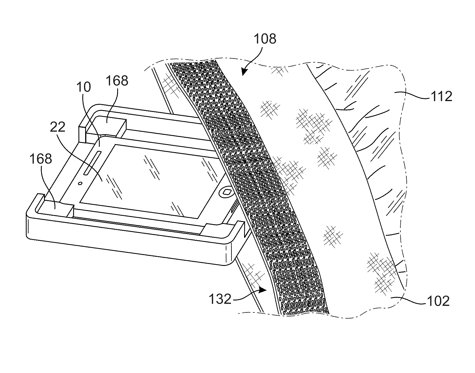
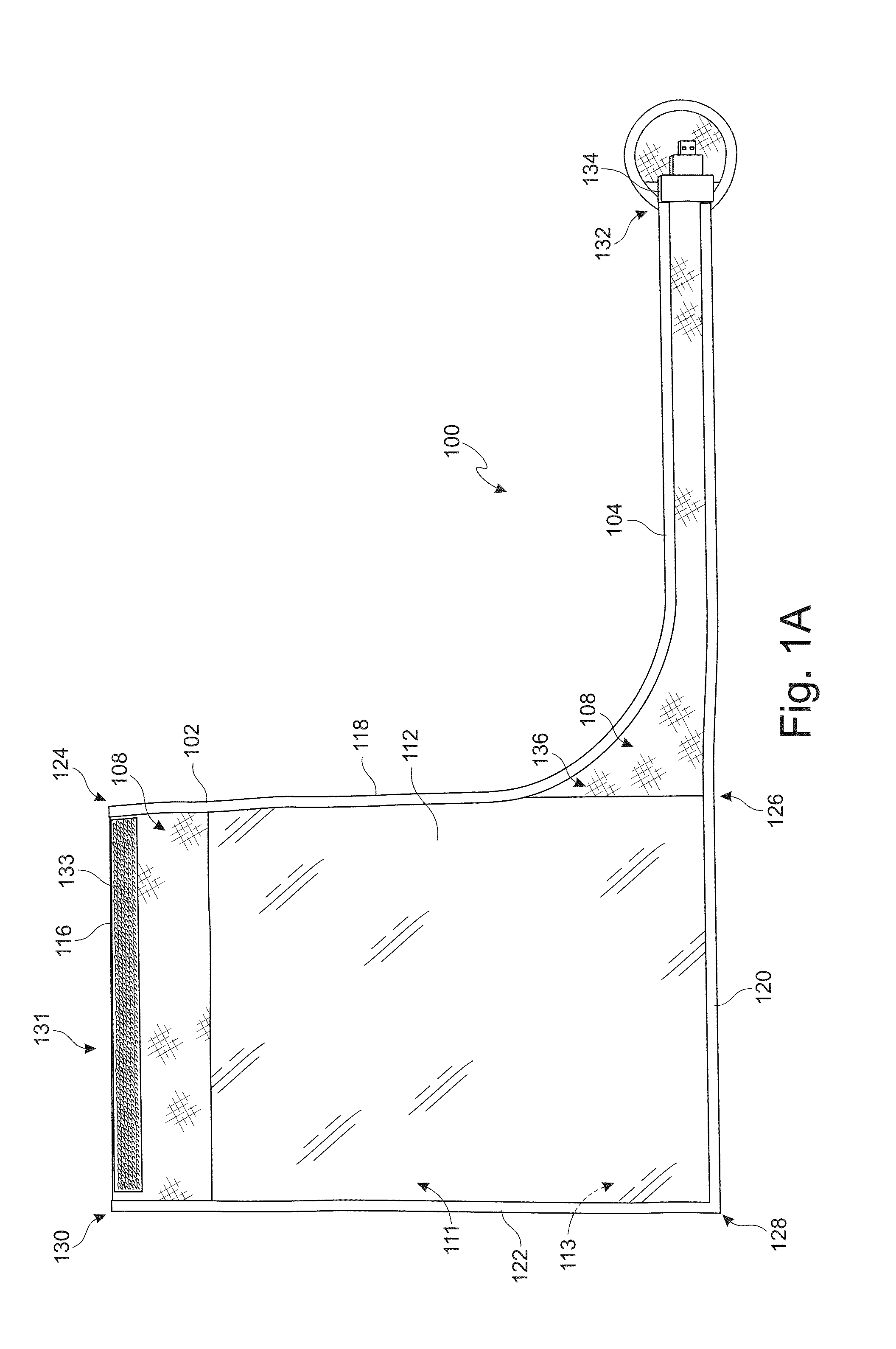
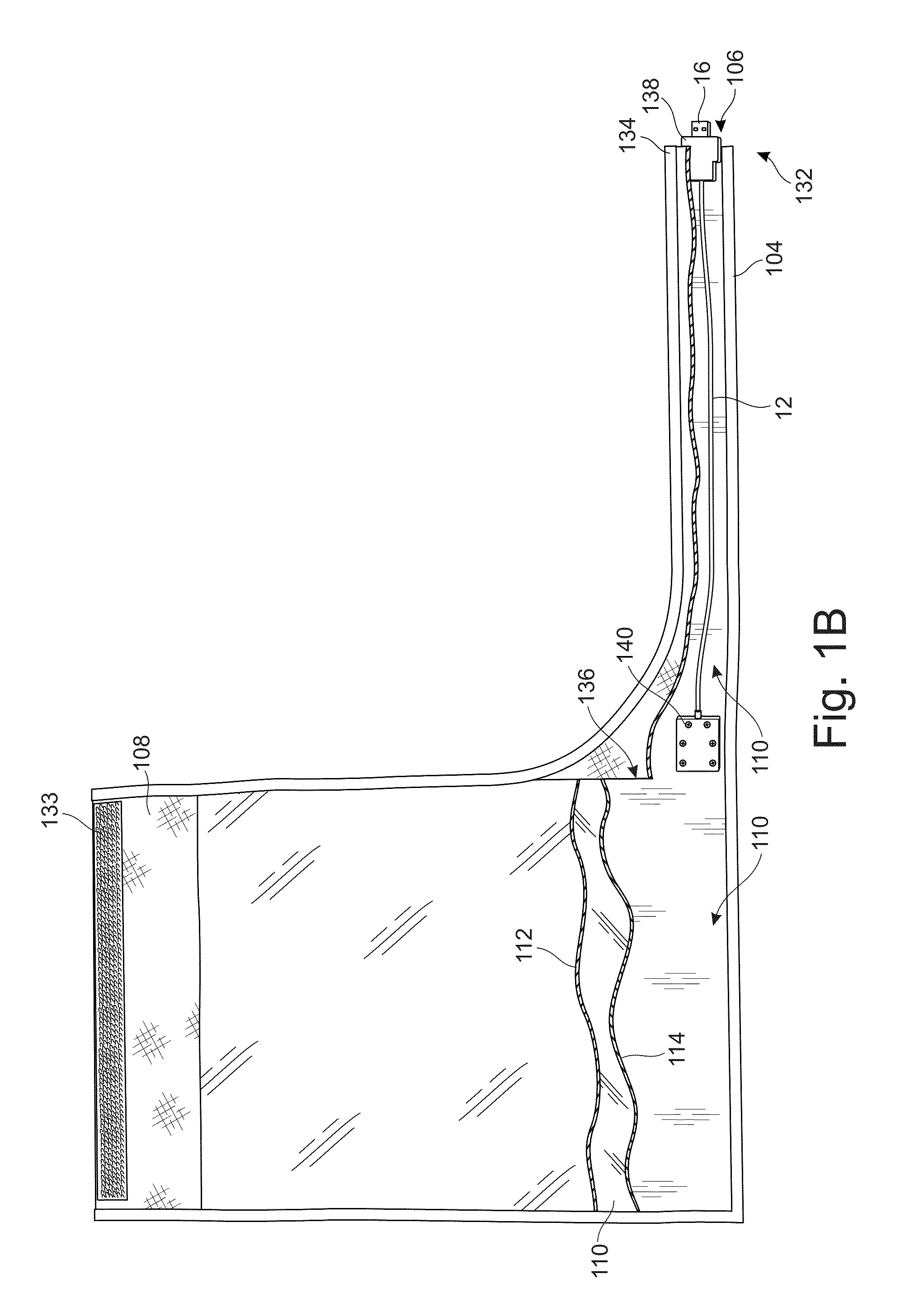
[0049]The present invention is a shielding device or EMI shield 100 to protect electronic devices 10 from electromagnetic interference, radiofrequency interference, and any other wireless signals (generally referred to as EMI) that may interfere with, modify, or otherwise, compromise information stored, received, or transmitted by an electr...


PUM

PropertyMeasurementUnit
Flexibilityaaaaaaaaaa
Metallic bondaaaaaaaaaa
Transparencyaaaaaaaaaa

Abstract

An electromagnetic interference shield having a main enclosure and at least one auxiliary enclosure. The auxiliary enclosure in the main enclosure and an interior that is continuous with each other. The auxiliary enclosure is made of elastic Faraday material. The outer layer and inner layer may be transparent to view the electronic device. An auxiliary cable with filtering mechanisms may be provided inside a sleeve to allow access and transfer of data from the electronic device while still in the main enclosure.

Description

CROSS-REFERENCE TO RELATED APPLICATION[0001]This patent application is a continuation-in-part of U.S. patent application Ser. No. 13 / 471,246, filed May 14, 2012, entitled “Portable Electromagnetic Interference Shield,” which claims the benefit of U.S. Provisional Patent Application No. 61 / 486,124, entitled “Portable EMI Shield,” filed May 13, 2011, and claims the benefit of U.S. Provisional Patent Application No. 61 / 824,317, filed May 16, 2013, entitled “Portable Electromagnetic Interference Shield with Flexible Cavity”, which applications are incorporated in their entirety here by this reference.[0002]A portion of the disclosure of this patent document contains material which is subject to copyright protection. The copyright owner has no objection to the facsimile reproduction by anyone of the patent document or the patent disclosure, as it appears in the Patent and Trademark Office patent file or records, but otherwise reserves all copyright rights whatsoever.TECHNICAL FIELD[0003]...

Claims


Application Information

Patent Timeline
IPC IPC(8): H05K9/00
CPCH05K9/0043Y10T29/49826
Inventor JUDY, RYAN
Owner E C RYAN INT
Why Eureka
Try Eureka